Saturday 31 August 2013

0 Comments
Posted in Arrangement, Art, Business

USB Powered Mobile Phone Battery Charger Circuit

Description 
 This simple circuit can give regulated 4.7 volts for charging a mobile phone. USB outlet can give 5 volts DC at 100mA current which is sufficient for the slow charging of mobile phones. Most of the Mobile Phone batteries are rated 3.6 volts at 1000 to 1300 mAh. These battery packs have 3 NiMh or Lithium cells having 1.2 volt rating. Usually the battery pack requires 4.5 volts at 300-500 mA current for fast charging.
But low current charging is better to increase the efficiency of the battery. The circuit described here provides 4.7 regulated voltage and sufficient current for the slow charging of the mobile phone. Transistor Q1 is used to give the regulated output. Any medium power NPN transistor like CL100, BD139, TIP122 can be used. Zener diode D2 controls the output voltage and D1 protects the polarity of the output supply. Front end of the circuit should be connected to a A type USB plug.
Connect a red wire to pin1 and black wire to pin 4 of the plug for easy polarity identification. Connect the output to a suitable charger pin to connect it with the mobile phone. After assembling the circuit, insert the USB plug into the socket and measure the output from the circuit. If the output is OK and polarity is correct, connect it with the mobile phone.
Circuit Diagram:
Parts
  • Q1 = BD139
  • D1 = 1N4001
  • D2 = 4.7V - 1/2W
  • R1 = 560R - 1/2W
  • C1 = 16V - 100uF 
 Note:
 If the polarity is incorrect, it will destroy the mobile battery. So take extreme care.

Source - http://www.extremecircuits.net/2010/02/usb-powered-mobile-phone-battery.html

    Friday 16 August 2013

    0 Comments
    Posted in Arrangement, Art, Business

    A Low Cost Hearing Aid Circuit

    Small and transportable unit, Useful for previous men and previous women

    This most economical, general-purpose electronic hearing help works off 3V DC (2x1.5V battery). The circuit will additionally be simply assembled on a veroboard. For easy assembling and repairs, use an 8-pin DIP IC socket for TDA2822M.

    Circuit Diagrams:
     A Low Cost hearing Aid Circuit
    Parts:
    P1 = 10K
    R1 = 2.2K
    R2 = 330K
    R3 = 680R
    R4 = 33R
    R5 = 100R
    R6 = four.7R
    R7 = 4.7R
    R8 = 220R
    C1 = zero.01uF-10V
    C2 = 100nF-63V
    C3 = four7uF-10V
    C4 = 10uF-10V
    C5 = 0.01uF-10V
    C6 = 100uF-10V
    C7 = 100nF-63V
    C8 = 100nF-63V
    D1 = Red LED
    Q1 = BC547
    IC1 = TDA2822M
    EP1 = Mono Earphone 32R
    SW1 = On-Off Switch

    Circuit Operation:

    In this circuit, transistor Q1 and related elements kind the audio signal preamplifier for the acoustic signals picked up via the condenser microphone and transformed into corresponding electrical signals. Resistor R5 and capacitor C3 decouple the facility supply of the preamplifier stage. Resistor R1 biases the interior circuit of the low-voltage condenser microphone for correct working. The audio output from the preamplifier stage is fed to the input of the medium-power amplifier circuit by method of capacitor C2 and quantity keep watch over P1.

    The medium-power amplifier section is wired round in style audio amplifier IC TDA2822M (not TDA2822). This IC, specially designed for moveable low-power utilitys, is readily available in 8-pin mini DIP bundle. Here the IC is wired in bridge configuration to pressure the 32-ohm general-purpose monophonic earphone. Red LED (D1) point outs the facility status. Resistor R8 restricts the running present of D1. The audio output of this circuit is 10 to 15mW and the quiescent present drain is below 1 mA.

    Source : www.electronsforu.com

    Thursday 15 August 2013

    0 Comments
    Posted in Arrangement, Art, Business

    170W power amplifier LM4651 and LM4652

    170 Watt power amplifier is a power amplifier that is built by IC LM4651 and LM4652.


    Part of this power amplifier driver using the LM4651 IC designed specifically for the purpose of the class AB amplifier driver with short circuit protection feature, containing under voltage, thermal shutdown protection and standby functions. Section 170 Watt power amplifier using LM4651 IC with a MOSFET power amplifier is equipped with temperature sensors that will be used by IC LM4651 as controlnya thermal signal. IC IC LM4651 and LM4652 are designed specifically to each other in pairs to create a class AB power amplifier with protection features are detailed. Detailed series of 170 Watt power amplifier can be seen in thethe following figure .

    170W power amplifier LM4651 and LM4652

    Power amplifier circuit requires supply voltages +22 V DC symmetrical 0-22V. Power Amplifier with IC LM4651 and LM4652 are often used in portable HiFi systems such as powered speakers, power subwoofer and car audio power Booter. D1, D2, D3 and D4 in series 170 watt power amplifier with LM4651 and LM4652 is a 22V zener diode.

    Wednesday 14 August 2013

    0 Comments
    Posted in Arrangement, Art, Business

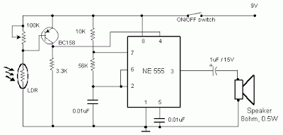
    Simple Light Sensor Alarm circuit with NE555

    Occurring this circuit sent out an alarm when its LDR sensor is exposed to light by sun or lamp. A 555 stable multivariate was used here which sent signal a tone of about 1kHz upon detecting light.The sensor when exposed by light completes the circuit and makes the 555 oscillate at about 1kHz with transistor to drive current.

    The sensor is also shown in the circuit diagram. It has to placed making an angle of about 30 – 45 degrees to the ground.

     Light Sensor Alarm circuit with NE555
     Sensitivity can be adjust with P1.
     This makes the sun light to flow through it to the ground and prevents the alarm from going on due to the stored light on the sensor

    Tuesday 13 August 2013

    0 Comments
    Posted in Arrangement, Art, Business

    Solar Relay

    With extended periods of bright sunshine and warm weather, even relatively large storage batteries in solar-power systems can become rather warm. Consequently, a circuit is usually connected in parallel with the storage battery to either connect a high-power shunt (in order to dissipate the excess solar power in the form of heat) or switch on a ventilation fan via a power FET, whenever the voltage rises above approximately 14.4 V. However, the latter option tends to oscillate, since switching on a powerful 12-V fan motor causes the voltage to drop below 14.4 V, causing the fan to be switched off.

    In the absence of an external load, the battery voltage recovers quickly, the terminal voltage rises above 14.4 V again and the switching process starts once again, despite the built-in hysteresis. A solution to this problem is provided by the circuit shown here, which switches on the fan in response to the sweltering heat produced by the solar irradiation instead of an excessively high voltage at the battery terminals. Based on experience, the risk of battery overheating is only present in the summer between 2 and 6 pm. The intensity of the sunlight falling within the viewing angle of a suitably configured ‘sun probe’ is especially high precisely during this interval.

    This is the operating principle of the solar relay. The trick to this apparently rather simple circuit consists of using a suitable combination of components. Instead of a power FET, it employs a special 12-V relay that can handle a large load in spite of its small size. This relay must have a coil resistance of at least 600 Ω, rather than the usual value of 100-200 Ω. This requirement can be met by several Schrack Components relays (available from, among others, Conrad Electronics). Here we have used the least expensive model, a type RYII 8-A printed circuit board relay. The light probe is connected in series with the relay. It consists of two BPW40 photo-transistors wired in parallel.

    Solar Relay Circuit DiagramThe type number refers to the 40-degree acceptance angle for incident light. In bright sunlight, the combined current generated by the two photo-transistors is sufficient to cause the relay to engage, in this case without twitching. Every relay has a large hysteresis, so the fan connected via the a/b contacts will run for many minutes, or even until the probe no longer receives sufficient light. The NTC thermistor connected in series performs two functions. First, it compensates for changes in the resistance of the copper wire in the coil, which increases by approximately 4 percent for every 10 ºC increase in temperature, and second, it causes the relay to drop out earlier than it otherwise would (the relay only drops out at a coil voltage of 4 V).

    Depending on the intended use, the 220-Ω resistance of the thermistor can be modified by connecting a 100-Ω resistor in series or a 470-Ω resistor in parallel. If the photo-transistors are fastened with the axes of their incident-angle cones in parallel, the 40-degree incident angle corresponds to 2 pm with suitable solar orientation. If they are bent at a slight angle to each other, their incident angles overlap to cover a wider angle, such as 70 degrees. With the tested prototype circuit, the axes were oriented nearly parallel, and this fully met our demands. The automatic switch-off occurs quite abruptly, just like the switch-on, with no contact jitter.

    This behavior is also promoted by the NTC thermistor, since its temperature coefficient is opposite to that of the ‘PTC’ relay coil and approximately five times as large. This yields exactly the desired effect for energizing and de-energizing the relay: a large relay current for engagement and a small relay current for disengagement. Building the circuit is actually straightforward, but you must pay attention to one thing. The photo-transistors resemble colorless LEDs, so there is a tendency to think that their ‘pinning’ is the same as that of LEDs, with the long lead being positive and the short lead negative. However, with the BPW40 the situation is exactly the opposite; the short lead is the collector lead. Naturally, the back-emf diode for the relay must also be connected with the right polarity. The residual current on cloudy days and at night is negligibly small.

    Monday 12 August 2013

    0 Comments
    Posted in Arrangement, Art, Business

    Build a Voice Scrambler or Descrambler Circuit Diagram

    This Voice Scrambler or De-scrambler Circuit Diagram uses an NE602 as an inversion mixer. U2 is set to run at about 2.5 to 3.5 kHz. U3 drives a loudspeaker. Because speech inversion scrambling is its own inverse, the circuit will also descramble . 

    Voice Scrambler or Descrambler Circuit Diagram

    Voice Scrambler or Descrambler Circuit Diagram

    Sunday 11 August 2013

    0 Comments
    Posted in Arrangement, Art, Business

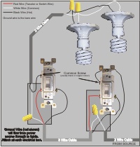
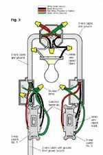
    Runs Switcheselectrical Wiring Forumgardenweb

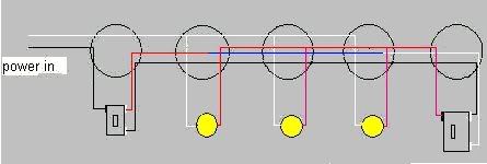
      Switch Wiring Diagrams on Handymanwire Wiring A 3 Way Or 4 Way Switch Handyman
    Handymanwire Wiring A 3 Way Or 4 Way Switch Handyman.


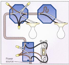
      Switch Wiring Diagrams on Way Switch Wiring Diagram 2
    Way Switch Wiring Diagram 2.


      Switch Wiring Diagrams on Double Pole Switch Wiring Diagram   Electrical Information Blog   Pc
    Double Pole Switch Wiring Diagram Electrical Information Blog Pc.


      Switch Wiring Diagrams on Mark The Three Way Switch Common Wire
    Mark The Three Way Switch Common Wire.


      Switch Wiring Diagrams on Stewmac Com 3 Way Lever Action Switch Free Information
    Stewmac Com 3 Way Lever Action Switch Free Information.


      Switch Wiring Diagrams on Installing A 3 Way Switch With Wiring Diagrams   The Home Improvement
    Installing A 3 Way Switch With Wiring Diagrams The Home Improvement.


      Switch Wiring Diagrams on Three Way Swiched Circuit Wiring Diagram
    Three Way Swiched Circuit Wiring Diagram.


      Switch Wiring Diagrams on Lights With 2 Way Switch Wiring Diagram
    Lights With 2 Way Switch Wiring Diagram.


      Switch Wiring Diagrams on Runs Between 3 Way Switches   Electrical Wiring Forum   Gardenweb
    Runs Between 3 Way Switches Electrical Wiring Forum Gardenweb.


      Switch Wiring Diagrams on Way Toggle Switch With 1 Volume Guitar Wiring Diagram   Arya
    Way Toggle Switch With 1 Volume Guitar Wiring Diagram Arya.


    Saturday 10 August 2013

    0 Comments
    Posted in Arrangement, Art, Business

    USB Keyboard Made from Old Typewriter

    Looking for a singular gift? Here’s an vintage typewriter which has been modified to function as a USB Keyboard for PC, Mac, and even iPad. That’s very cool, isn’t it?

    Hacks and Mods: USB Keyboard Made from Old Typewriter

    In the sector of obsolescence, this USB typewriter is a groundbreaking innovation. It does no longer trade the outward look of the typewriter and is simple to put in because there is no messy wiring. The three elements of the USB typewriter are the Sensor board, the USB switches, and the Reed Switches.

    It works like a normal typewriter with all letters, numerals, and punctuation marks as neatly as shift, house, and return carriage. It’s a greater addition to your house place of business.

    Friday 9 August 2013

    0 Comments
    Posted in Arrangement, Art, Business

    Car Battery 12v Charger

    The usual chargers of battery automotive, are simple and cheap appliances that charge continuously the battery, with a rythm of few amperes, for the time where the appliance is ON. If the holder do not close in time the charger, the battery will overcharge and her electrolytic faculty are lost with evaporation or likely exists destruction of her elements. The charger of circuit exceeds these faults. It checks electronic the situation of charge of battery and it has circuit of control with retroaction, that forces the battery charge with biggest rythm until charge completely. 
     
    Circuit diagram:
    Car_baterry_charger Circuit Diagram
    Car Battery 12v Charger Circuit Diaram
    When charge completely, it turns on one RED led (LD2). The charger has been drawn in order to charge batteries of 12V, ONLY. What should watch it from what it manufactures the circuit, they are the cables that connect the transformer with the circuit and in the continuity the battery, should they are big cross-section, so that heat when it passes from in them the current of charge and also they do not cause fall of voltage at the way of current through them.
    Adjustment
    After assembling of the circuit, adjust TR1 to null value, power-up and make the following adjustments :-
    1. Without connecting the battery check that the 2 LED?s are turned on.
    2. Connect a car battery to the circuit and check that LD2 is OFF and a current (normally 2A to 4A) is flowing to the battery.
    3. Adjust TR1 until LD2 turns ON and the charge current is cut.
    4. Adjust TR1 to null value and charge the battery using the hydrometer technique (if you do not have or do not know how to use a hydrometer, then use a good condition battery and charge).

    Carefully adjust TR1 so that LD2 begins to turn ON and the charge current falls to a few hundred milliamps (mA). If TR1 is set correctly then in the next round of charging you will noticed LD2 begin to flicker as the battery is being charged. When battery is completely charged, LD2 turns ON completely.TR1 does not need further adjustment anymore. Q1 is connected in line with the battery and is fired by R3, R4 and LD2. The R2, C1, TR1 and D2 sense the voltage of the battery terminal and activate Q2 when the voltage of the battery terminal exceeds the value predetermined by TR1.

    When an uncharged battery is connected, the terminal voltage is low. Under this circumstance, Q2 is turned OFF and Q1 is fired in each half cycle by R3, R4 and LD2. The Q1 functions as a simple rectifier and charges the battery. If the battery terminal voltage is increased above the level that had been fixed by TR1, then Q2 shifts the control of Q1 gate. This deactivates Q1 and cuts off the current supply to the battery and turns LD2 ON indicating that the charge has been completed. Q1 and bridge rectifier GR1 should be mounted on heatsinks to prevent overheating. M1 is a 5A DC ammeter to measure the charge current.

    Source :users.otenet.gr

    Thursday 8 August 2013

    0 Comments
    Posted in Arrangement, Art, Business

    Electrical Floorplans Power Voltage Structured Wiring

    Electrical Wiring on 1964 Gmc Truck Electrical System Wiring Diagram   Circuit Schematic
    1964 Gmc Truck Electrical System Wiring Diagram Circuit Schematic.


    Electrical Wiring on Free Wiring Diagrams   Download Free Wiring Schematics
    Free Wiring Diagrams Download Free Wiring Schematics.


    Electrical Wiring on Home Electrical Wiring   New Home  Remodels  Additions   As You Wish
    Home Electrical Wiring New Home Remodels Additions As You Wish.


    Electrical Wiring on Wiring A Switched Outlet Wiring Diagram   Electrical Online
    Wiring A Switched Outlet Wiring Diagram Electrical Online.


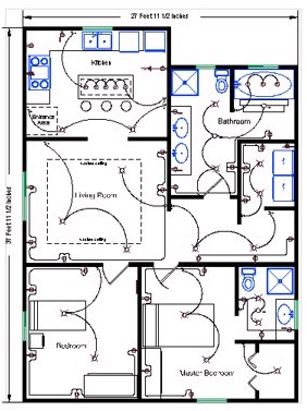
    Electrical Wiring on Electrical Floorplans With Power  Low Voltage And Structured Wiring
    Electrical Floorplans With Power Low Voltage And Structured Wiring.


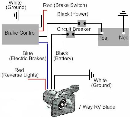
    Electrical Wiring on Electric Trailer Brake Controller Wiring
    Electric Trailer Brake Controller Wiring.


    Electrical Wiring on Kawasaki Vulcan Vn750 Electrical System And Wiring Diagram   Circuit
    Kawasaki Vulcan Vn750 Electrical System And Wiring Diagram Circuit.


    Electrical Wiring on Electricians  Electrical Installation   Electrical Contractors In
    Electricians Electrical Installation Electrical Contractors In.


    Electrical Wiring on Wiring Diagram
    Wiring Diagram.


    Electrical Wiring on Residential Circuit Diagram Electrical Wiring Information
    Residential Circuit Diagram Electrical Wiring Information.


    Tuesday 6 August 2013

    0 Comments
    Posted in Arrangement, Art, Business

    Precision Full Wave Ac Dc Converter Circuit Diagram

    A dc level is produced that corresponds to the ac input rms value (if sine wave), -i set the gain of IC2 to 1.11. This factor is the average-to-rms conversion factor. IC1 and IC2 act as a full-wave rectifier circuit, with Dl and D2. 

    Precision Full-Wave Ac/Dc Converter Circuit Diagram


    Precision Full-Wave Ac/Dc Converter Circuit Diagram

    Monday 5 August 2013

    0 Comments
    Posted in Arrangement, Art, Business

    555 Timer Modeling


    The
    555 IC timer chip is widely used as both a monostable and astable
    multivibrator. Originally introduced by Signetics using bipolar
    technology, the 555 is now available from several manufacturers in
    bipolar and CMOS technology.


    Sunday 4 August 2013

    0 Comments
    Posted in Arrangement, Art, Business

    TA8210AH car audio amplifier circuit

    TA8210AH 200W car amplifier schematic
    IC TA8210AH By using this you can apply a series of audio power amplifier is the car audio system. In general, all the speakers in the car using a subwoofer speaker, and woofer. Because the car is not big room so the sound is being required is not too high.


    Audio amplifier circuit can work at a minimum voltage 12-volt DC, if supplied under voltage 12-volt amplifier work will be less than the maximum. This amplifier output power up to 200W or 2 x 100W stereo with 8 ohm impedance.

    200W car amplifier schematic

    Part List :

    Resistor
    R1 =1K
    R2 =50K trim
    R3 =1K
    R4 =50K trim
    R5 =680R
    R6 =680R
    R7 =150K
    R8 =2R2
    R9 =2R2
    R10=2R2
    R11=2R2

    Capacitor
    C1 =1uF
    C2 =1uF
    C3 =47uF
    C4 =47uF
    C5 =100n/400V
    C6 =220uF
    C7 =220uF
    C8 =100n/400V
    C9 =100n/400V
    C10=100n/400V

    Intregated Circuit
    IC1=TA8210AH

    Connector
    X2-3=in R
    X2-2=gnd
    X2-1=in L
    X1-1,X1-2=Out R
    X1-3,X1-4=Out L

    Saturday 3 August 2013

    0 Comments
    Posted in Arrangement, Art, Business

    Simple Audio Filter Analyzer Circuit

    When this circuit is connected to a filter and an oscilloscope, the scope displays the filter`s frequency response. A frequency that sweeps from low to high is applied to a filter. An oscilloscope is triggered by* the start of the sweep and ends its trace at the highest frequency of the sweep. The filter output goes to the vertical amplifier of the oscilloscope. Using bandpass filters as an example, as the bandpass frequency is approached, reached, and passed, the scope follows the peaking output and draws the response curve. A neat effect! The 566 VCO (Ul) produces a VLF triangle wave to frequency modulate the next stage. 

     Audio Filter Analyzer Circuit Diagram

    Audio Filter Analyzer Circuit

    It also produces a square wave to externally trigger the scope. Op amp U2 (a 741 unit) optimizes the amplitude and the dc component. Another VCO (U3) produces the actual sweeping triangle wave. Its frequency is selectable via SI. Op amp U4 (another 741 op amp) is set up as a bandpass filter and has been included as an example filter. Finally, diode D1 chops off the bottom half of the output, and leaves a nice bell curve. lb set up and operate, power-up the circuit and scope. Set the scope`s TIME/CM to 50 ms/cm. Set the VOLTS/CM control to 2 V. Attach a probe from the circuit`s trigger to the scope`s external trigger input. Set the triggering mode to normal, external. Attach a probe from the vertical amplifier to TP1. You`ll see a diagonal line that runs across the CRT. Input coupling should be set to dc. Adjust the triggering level until the diagonal runs from the upper left to the lower right of the CRT to ensure a displayed sweep from low to high. Now, disconnect the probe from TP1 and attach it to the filter output past the diode.

    Friday 2 August 2013

    0 Comments
    Posted in Arrangement, Art, Business

    Ni cad Charger Circuit Diagram

    Ni-cad charger with current and voltage limiting. Lamp LI will glow brightly and the LED will be out when the battery is low and being charged, but the LED will be bright and the light bulb dim when the battery is almost ready. Ll should be a light bulb rated for the current you want (usually the battery capacity divided by 10). Diode D1 should be at least 1 A, and Z1 is a 1W zener diode with a voltage determined by the full-charge battery voltage minus 1 V. After the battery is fully charged, the circuit will float it at about battery capacity divided by 100 mA.

    Ni-cad Charger Circuit Diagram


    Ni-cad Charger Circuit Diagram

    Thursday 1 August 2013

    0 Comments
    Posted in Arrangement, Art, Business

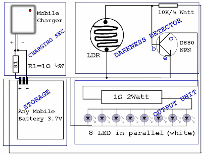
    Reuse Old Mobile Phone Battery for LED lighting

    Normally mobile batteries have a lifespan of 2-5 years under normal usage. But then we have to replace them. Nowadays there are cheap replacement batteries which cost no more than 1$. But these low cost batteries run only 6-12 months. What to do with the used batteries, which can’t be reused in mobiles? Well, easy solution is to use the batteries in a circuit that requires less current. We can use them for LED lighting.

    Do you have old unusable Mobile battery?
    Hacks and Mods: Reuse Old Mobile Phone Battery for LED lighting
    Normally mobile batteries have a lifespan of 2-5 years under normal usage. But then we have to replace them. Nowadays there are cheap replacement batteries which cost no more than 1$. But these low cost batteries run only 6-12 months. What to do with the used batteries, which can’t be reused in mobiles?
    Hacks and Mods: Reuse Old Mobile Phone Battery for LED lighting
    Well, easy solution is to use the batteries in a circuit that requires less current. We can use them for LED lighting. Thus your automatic lighting emergency light is ready which runs by your waste Mobile Battery.

      Total Pageviews