Friday 31 May 2013

0 Comments
Posted in Arrangement, Art, Business

Trac Vehicle Wiring Trac Outdoor Products T10135iboats

Vehicle Wiring Products on Car Power Seats Control Wire Harness   Dongguan Yacenter Electric Co
Car Power Seats Control Wire Harness Dongguan Yacenter Electric Co.


Vehicle Wiring Products on Vwp   Brake Pipes   Fittings
Vwp Brake Pipes Fittings.


Vehicle Wiring Products on Audio Amplifier Kits  Audio Amplifier Brand  Model Number In Tomcatso
Audio Amplifier Kits Audio Amplifier Brand Model Number In Tomcatso.


Vehicle Wiring Products on Car Amplifier Repair  Car Amplifier Brand  Model Number In Tomcatso
Car Amplifier Repair Car Amplifier Brand Model Number In Tomcatso.


Vehicle Wiring Products on Http   Www Vehicle Wiring Products E   Connectors Php
Http Www Vehicle Wiring Products E Connectors Php.


Vehicle Wiring Products on Trac Vehicle Wiring Kit   Trac Outdoor Products T10135   Iboats
Trac Vehicle Wiring Kit Trac Outdoor Products T10135 Iboats.


Vehicle Wiring Products on Http   Www Vehicle Wiring Products E   Hoto Dig05 Jpg
Http Www Vehicle Wiring Products E Hoto Dig05 Jpg.


Vehicle Wiring Products on For Car Wiring Harness  For Car Wiring Harness Brand Name  Type  Model
For Car Wiring Harness For Car Wiring Harness Brand Name Type Model.


Vehicle Wiring Products on Car Amplifier Wiring Kit With Different Kinds Of Power Cable   Speaker
Car Amplifier Wiring Kit With Different Kinds Of Power Cable Speaker.


Vehicle Wiring Products on 304  330  334  336  342  344  346  452  367  368  391  392
304 330 334 336 342 344 346 452 367 368 391 392.


Wednesday 29 May 2013

0 Comments
Posted in Arrangement, Art, Business

Electronic Cricket Match Game

This electronic cricket is a present for Kids. This simple battery powered circuit can be used to play Cricket Match with your friends. Each LED in the circuit indicates various status of the cricket match like Sixer, Run out, Catch etc. The Circuit uses two ICs ,one in the Astable mode and the second in the display driver mode. IC1 is wired as an Astable Multivibrator with the timing elements R1, R2 and C1. With the shown values of these components very fast output pulses are generated from the Astable.

Output from IC1 passes into the input of IC2 which is the popular Johnson Decade counter CD4017. It has 10 outputs. Of these 8 outputs are used. Output 9 ( pin9) is tied to the reset pin 15 to repeat the cycle. When the input pin 14 of IC2 gets low to high pluses, its output turns high one by one. Resistor R3 keeps the input of IC2 low in stand by state to avoid false indications.

Electronic Cricket Circuit Diagram
Cricuit Project: Electronic Cricket Match Game
When the Push Switch S1 is pressed momentarily, the Astable operates and all the LEDs run very fast sequentially. When S1 is released, any one of the LED stands lit which indicates the status of the match. For example, if LED D7 remains lit, it indicates Sixer and if LED 8 remains lit, it indicates Catch out. Label each LED for its status as shown in the diagram. Pressing of S1 simulates Bowling and Running LEDs indicates running of Batsman.

Monday 27 May 2013

0 Comments
Posted in Arrangement, Art, Business

Blinking LED Circuit Diagram

This is a blinking LED circuit diagram.Here I have used common IC NE555.If you want to change the speed of this circuit you can change the value of R2.Then you can do that.


Note

* Use a PCB to build this circuit
* You can operate this circuit with 9V

Sunday 19 May 2013

0 Comments
Posted in Arrangement, Art, Business

Simple electronics Code Lock System

SIMPLE ELECTRONIC
CODE LOCK
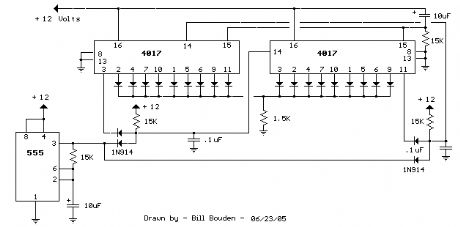
The circuit diagram of a simple electronic
code lock is shown in figure.
A 9-digit code number is used
to operate the code lock.
When power supply to the circuit is
turned on, a positive pulse is applied to
the RESET pin (pin 15) through capacitor
C1. Thus, the first output terminal
Q1 (pin 3) of the decade counter IC (CD
4017) will be high and all other outputs
(Q2 to Q10) will be low. To shift the high
state from Q1 to Q2, a positive pulse must
be applied at the clock input terminal (pin
14) of IC1. This is possible only by pressing
the push-to-on switch S1 momentarily.
On pressing switch S1, the high state
shifts from Q1 to Q2.


Now, to change the high state from
Q2 to Q3, apply another positive pulse at
pin 14, which is possible only by pressing
switch S2. Similarly, the high state can
be shifted up to the tenth output (Q10)
by pressing the switches S1 through S9
sequentially in that order. When Q10 (pin
11) is high, transistor T1 conducts and
energises relay RL1. The relay can be
used to switch ‘on’ power to any electrical
appliance.
Diodes D1 through D9 are provided
to prevent damage/malfunctioning of the
IC when two switches corresponding to
‘high’ and ‘low’ output terminals are
pressed simultaneously. Capacitor C2 and
resistor R3 are provided to prevent noise
during switching action.
Switch S10 is used to reset the
circuit manually.

Switches S1 to S10
can be mounted on a keyboard panel,
and any number or letter can be used to
mark them. Switch S10 is also placed
together with other switches so that any
stranger trying to operate the lock frequently
presses the switch S10, thereby
resetting the circuit many times. Thus,
he is never able to turn the relay ‘on’. If
necessary, two or three switches can
be connected in parallel with S10 and
placed on the keyboard panel for more
safety.
A 12V power supply is used for the
circuit. The circuit is very simple and can
be easily assembled on a general-purpose
PCB. The code number can be easily
changed by changing the connections to
switches (S1 to S9).

Thursday 16 May 2013

0 Comments
Posted in Arrangement, Art, Business

Ground Loops

What is ground loop ?
A ground loop occurs when there is more than one ground connection path between two pieces of equipment. The duplicate ground paths form the equivalent of a loop antenna which very efficiently picks up interference currents. Lead resistance transforms these currents into voltage fluctuations. As a consequence of ground-loop induced voltages, the ground reference in the system is no longer a stable potential, so signals ride on the noise. The noise becomes part of the program signal.
Ground loop is a common wiring conditions where a ground current may take more than one path to return to the grounding electrode at the SERVICE PANEL. AC powered computers all connected to each other through the ground wire in common building wiring. Computers may also be connected by data communications cables. Computers are therefore frequently connected to each other through more than one path. When a multi-path connection between computer circuits exists, the resulting arrangement is known as a "ground loop". Whenever a ground loop exists, there is a potential for damage from INTER SYSTEM GROUND NOISE.
A ground loop in the power or video signal occurs when some components in the same system are receiving its power from a different ground than other components, or the ground potential between two pieces of equipment is not identical.
Usually a potential difference in the grounds causes a current to flow in the interconnects. This in turn modulates the input of the circuitry and is treated like any other signal fed through the normal inputs. Here is an example situation where two grounde equipments are interconnected though signal wire ground and the mains grounding wire. In this situation there is 1A current flowing flowing in the wire which causes 0.1V voltage difference between those two equipemt grounding points.
Ground Loops Explanation

Example of groundloop problem in system interconnection
Because there is voltage difference between the ewuipments, the signal in the interconnection wire sees that difference added to signal. This canbe heard as humming noise on the wire because the AC current cause the voltage difference of those ground potentials to be also AC voltage. This is one reason for this 50 Hz or 60 Hz noise you hear in the audio signal (or see in video signal as annoying horizonal bars).
Another problem is the current flowing in the signal cable grounding wire. This current passes though the cable and through the equipment. Of the way the curren parsses is not weel designed this can cause lots noise to the equipment or other kind of problems (like computer lockups). Lots of designers count on ground being ground and do not optimize their design to eliminate their sensitivity to ground noise. If you are a product desiger remeber to take care that ground loop current does not cause problems in your equipment by designing proper grounding scheme inside the equipment.

Why ground loop is a problem ?

Ground loop is a common problem when connecting multiple audio-visual system components together, there is a good change of making a nasty ground loops. Ground loop problems are one of the most common noise problems in audio systems. Typical indication of the ground loop problem is audible 50 Hz or 60 Hz (depends on mains voltage frequency used in your country) noise in sound. Most common situation where you meet ground loop problems are when your system includes equipment connected to earthed elecric outlet and antenna network or equipments connected to different grounded outlets around the room.
Everything connected to a single mains earth, which is usually connected to all the earth pins in all the power sockets in one room. Then antenna network is also grounded to same grounding point. This would normally be okay, as the grounding is only connected to each other in a star-like fashion from a central earth wire (leading to the real Earth via a grounding cable or metal pipe) earth cables run through your power cables into the equipment.
Once you take into account that some of your equipment is linked with shielded cable you are quite likely to face some problems. Currents could quite possibly run from one piece of equipment, into the earth cable, into another piece of equipment, then back to the first piece via a shielded audio cable. That wire loop can also pick up interference from nearby magnetic fields and radio transmitters.
The result is that the unwanted signal will be amplified until it is audible and clearly undesireable. Even voltage differences lower than 1 mV can cause annoying humming sound on your audio system.
A problem with audible noise coming from your audio system when other electronic components (fridge, water cooler, ect.) could be the result of of a contaminated ground/neutral conductor in your A/C wiring and a ground loop in uour audio system. This can happen when certain type of devices come on. Typically their power supplies are non-linear and throw garbage back onto the neutral and/or ground conductors. Usually line conditioners or UPS devices will not do anything to help solve this problem.

Common Causes for Computer System Problems

Many times when a user thinks that his system is bad or has gone bad the fault is electrical or magnetic in nature. Monitor problems are very often caused by nearby magnetic fields, neutral wire harmonics, or conducted/transmitted electrical noise. Intermittent lockups of computers are very often the caused by a Ground Loop, an electrical phenomena that sometimes manifests itself when a system and its peripherals are improperly plugged into different electrical circuits. Many dont even know if their wall outlet is properly wired and grounded, an absolute necessity for a computer and peripheral to operate reliably and safely.
Have you ruled out Ground Loops in your computer system ? Ground loops can cause problems to LAN connections if not properly wired. A ground loop caused by RS-232 connection to other computer can cause computer lockups.

When ground loop is not a problem
Ground loop does not cause problems when all of the following thing are true:
* None of the wires in the loop carry any current
* The loop is not exposed to external changing magnetic fields
* There is no radio frequency interference nearby
If there is any current folowing in any wires, there is then some potentital difference which causes current to flow in other wires also which causes problems. The loop will also act as coil and pick current from the changing magnetic fields around it. Wire loop acts also like an antenna picking up radio signals.
What size of ground potential difference problems we are talking about ?
Literature is speaking about Common Mode Noise of 1 to 2 Volt in "well grounded" plants and over 20 Volts in "poorly grounded" plants. Literature is also speaking of the current measured on a main service grounding (in a large building) in terms of Amps.

Where does this current and voltage difference come from ?
Current leakage of condensators between hot and ground and between neutral and ground, in for instance main filters, cause current in ground wires (and ground loops). The leakage current is typically measures in milliamperes (typically less than 1 mA in computer equipments) per equipment. When you sum up maybe hundreds of such equipments you can easyly get amperes.
The capacitance between line and ground of large heaters and motors, for example, can be much larger than the capacitance in filter capacitors. Currents from this source are usually of the order of 1 amp (rather than 0.1 A or 10 A)
Even a very small induced voltage can cause a very large current in a ground conductor loop, because the resistance (and inductance) are very low. These currents can indeed be tens of amps. Current induction can be caused for example by cables carrying high currents and from transformers.

What those grounding currents and voltage differences can do ?
Small voltage differences just cause noise to be added to the signals. This can cause humming noise to audio, interference bars to video signals and transmission errors to computer networks.
Higher currents can cause more serious problems like sparking in connections, damages equipment and burned wiring. My own experience on th field is limited to sparking connectors, heating cables and damaged computer serial port cards. I have read about burned signal cables and smoking computers because of the ground differentials and large currents caused by them. So be warned about this potential problem and do not do any stupid installation

Tuesday 14 May 2013

0 Comments
Posted in Arrangement, Art, Business

Knowing electrical switch


In energy technological innovation, a change is a handled factor that can break a handled routine, uncomfortable the present or direction-finding it from one conductor to another.[1][2]

The most familiar way of change is a independently handled electromechanical system with one or more locations of electrical powered handled managed handled connections, which are attached to exterior journey.

Each set of connections can be in one of two states: either "closed" significance the connections are in contact with and energy can activity between them, or "open", significance the connections are divided and the change is nonconducting. The procedure actuating the alteration between these two declares (open or closed) can be either a "toggle" (flip change for ongoing "on" or "off") or "momentary" (push-for "on" or push-for "off") kind.
A change may be straight handled by a personal as a management indication to a system, such as a PC key pad choice, or to management energy activity in a routine, such as a light change.

 Instantly handled changes can be used to management the activities of gadgets, for example, to indicate that a accessibility has acquired its finish start place or that a system product is in a place to agree to another workpiece. Changes may be handled by procedure factors such as pressure, heated extensive extensive variety, activity, present, current, and energy, doing as receptors in a procedure and used to right away management a system. For example, a heated extensive extensive variety is a temperature-operated change used to management a heating procedure. A change that is handled by another energy routine is known as a web link. Huge changes may be a little bit handled by a website produce procedure. Some changes are used to personal energy from a system, offering a identifiable factor of fulfillment that can be padlocked if necessary to avoid exclusive function of a system during servicing, or to avoid energy surprise.

Monday 13 May 2013

0 Comments
Posted in Arrangement, Art, Business

VHF field strength meter

This is a simple and low cost wide band VHF field strength meter. The field strength is measured by converting the radio signal to DC and measuring it.


The RF signal will be picked up by the coil and rectified by the diode D1.Even a very small DC voltage is sufficient to alter the biasing of FET and it will be reflected in the meter as an indication of the presence of a radio signal. The meter can be calibrated by adjusting the preset R2 to make meter M1 read ZERO in the absence of any radio signal. This circuit is not very sensitive, but can sense radio signals from hand held FM transmitters up to a distance of few meters( ideal for theoretical demonstrations).

* The circuit can be assembled on a general purpose PCB.
* Use a 9V PP3 battery for powering the circuit.
* Use a 250uA FSD current meter for M1.Using a lower FSD meter will improve sensitivity.
* The coil L1 can be made by making 6 turns of 20 SWG enameled copper wire on a inch plastic former.
* The antenna can be a telescopic whip antenna.

Sunday 12 May 2013

0 Comments
Posted in Arrangement, Art, Business

Whistle Responder

This device beeps intermittently for approx. two seconds when a person in a range of about 10 meters emits a whistle.
The first two inverters contained in IC1 are used as audio amplifiers. IC1A amplifies consistently the signal picked-up by the small electret-microphone and IC1B acts as a band-pass filter, its frequency being centered at about 1.8KHz. The filter is required in order to select a specific frequency, the whistles one, stopping other frequencies that would cause undesired beepers operation.

IC1C is wired as a Schmitt trigger, squaring the incoming audio signal. IC1D is a 2 second (approx.) monostable driving the astable formed by IC1E & IC1F. This oscillator generates a 3 to 5Hz square wave feeding Q1 and BZ1, thus providing intermittent beepers operation. Parts:
R1 22K 1/4W Resistor
R2 10K 1/4W Resistor
R3 4M7 1/4W Resistor
R4,R8 100K 1/4W Resistors
R5 220R 1/4W Resistor
R6 330K 1/4W Resistor
R7 47K 1/4W Resistor
R9 2M2 1/4W Resistor
R10 1M5 1/4W Resistor
C1,C5 47nF 63V Polyester or Ceramic Capacitors
C2,C3 10nF 63V Polyester Capacitors
C4,C6 1µF 63V Electrolytic Capacitors
D1,D2 1N4148 75V 150mA Diodes
IC1 4049 Hex Inverter IC
Q1 BC337 45V 800mA NPN Transistor
MIC1 Miniature electret microphone
BZ1 Piezo sounder (incorporating 3KHz oscillator)
B1 2.8 or 3V Battery (see notes)

Sunday 5 May 2013

0 Comments
Posted in Arrangement, Art, Business

Build A Relay Toggle Switch

Half of RL1 and RL2 manipulate the switching and the other is connected to an application. Relays are 200 ohms above ground and at one point are referenced to positive that turns them off.

Description:

RL1 (which is off) applies plus voltage from its armature and latches RL2 “on”. The application terminals are set to [A]. The condition changes when S1 is activated, voltage is applied to RL2 latching RL1 “on” releasing S1 turns RL2 “off”. RL2’s armature is then directed to R1. Terminals are set to [B].

When S1 is pressed again, the relays negative side are referenced to positive, RL1 turns “off” (there’s no current flow). RL2 turns “on” when S1 is released, terminals are set to [A]. There is slight lag between relays depending on how long S1 is held.

Relay Toggle Switch Circuit Diagram

Note: 

If different relays are used, adjustment of R1’s value may be required. For example, OEG relays (12vdc, 270 ohm coil) need R1 at 60 - 70 ohms. The prime motivation for this design was to avoid using toggle switches for my audio control panel. Another plus, it can be controlled from a remote transmitted pulse.

Thursday 2 May 2013

0 Comments
Posted in Arrangement, Art, Business

Simple Multiple Continuity Tester

http://s.eeweb.com/members/circuit_projects/blog/2012/01/21/circuit-continuity-tester-using-op-amps-1327172100.gifThe continuity tester is a handy adjunct to an ohmmeter. The unit or component whose continuity is to be checked is connected between terminals E1 and E2 (which may be probes or croc clips). The test current then flowing through the unit/component on test causes a potential drop across resistor R2, which is applied to the non-inverting input of buffer IC2. The output of the op amp is applied to transistor T1, in the emitter circuit of which there are a number of parallel-connected light-emitting diodes. Each LED is in series with a zener diodes and a resistor. The zener diodes have dissimilar zener voltages as shown in the diagram. When the drop across R2 exceeds the sum of base-emitter voltage of T1, a zener voltage, and the threshold voltage of the LED in series with that zener diode, the relevant LED lights. which resistance value of the unit/component on test a particular LED lights. Bear in mind, however, that these values depend to some extent on the type of LED, and also that the zener voltages are subject to tolerances. Serious deviations may be corrected by the addition of a standard diode or a Schottky diode. It is also possible to add branches to individual requirements, or to use a bar display instead of LEDs. It is important that the op amp used has a rail-to-rail output since the input voltages as well as the output may rise to the peak supply voltage. This requirement is met by the MAX4322 as used in the prototype.
0 Comments
Posted in Arrangement, Art, Business

10 Channel LED Sequencer

http://www.seekic.com/uploadfile/ic-circuit/s201210221452903.gif
this is how to Build 10 Channel LED Sequencer may you have another idea, will be good if you share here.

Wednesday 1 May 2013

0 Comments
Posted in Arrangement, Art, Business

LED Camera

The process mentioned below shows how we can convert the LEDs to the light sensors so that it can be used for many other purposes also. Read on to know more about this.As the Blinkenlight Shield has 20 of them, 20 pixel camera can be developed by it. After performing the experiment, it is recommended to reset the jumper setting to default. LED or Light Emitting diodes usually act as the photo diodes and are optimized to produce the light.
Hacks and Mods: DIY LED Camera

LEDs can be used to make the light detectors that can be helpful in various conditions. The idea behind this is to reverse bias the diodes by turning the IO pins to output low so that the LEDs used will act as capacitors and will not be conducted. The current produced due to the LED is very small, and the photo current produced discharges the LED capacitors. After charging, the IO pins have to be switched to high Z so as to generate the light. The light produced and the current are directly proportional to each other.


After the discharging of capacitors, the pin will move towards high from low. By measuring the time taken for discharge, the amount of light reached by the LED can be calculated. After processing all the LEDs, they can be used in a serial line but it should be taken care of that this is done in a separate step to avoid any mistake in measuring the discharge time.

    Total Pageviews