Monday, 30 September 2013

0 Comments
Posted in Arrangement, Art, Business

Power Flip Flop Using A Triac

Modern electronics is indispensable for every large model railroad system, and it provides a solution to almost every problem. Although ready-made products are exorbitantly expensive, clever electronics hobbyists try to use a minimum number of components to achieve optimum results together with low costs. This approach can be demonstrated using the rather unusual semiconductor power flip-flop described here. A flip-flop is a toggling circuit with two stable switching states (bistable multivibrator). It maintains its output state even in the absence of an input pulse.

Flip-flops can easily be implemented using triacs if no DC voltage is available. Triacs are also so inexpensive that they are often used by model railway builders as semiconductor power switches. The decisive advantage of triacs is that they are bi-directional, which means they can be triggered during both the positive and the negative half-cycle by applying an AC voltage to the gate electrode (G). The polarity of the trigger voltage is thus irrelevant. Triggering with a DC current is also possible. Figure 1 shows the circuit diagram of such a power flop-flop. A permanent magnet is fitted to the model train, and when it travels from left to right, the magnet switches the flip-flop on and off via reed switches S1 and S2.

Power Flip-Flop Using a Triac circuit schematic

In order for this to work in both directions of travel, another pair of reed switches (S3 and S4) is connected in parallel with S1 and S2. Briefly closing S1 or S3 triggers the triac. The RC network C1/R2, which acts as a phase shifter, maintains the trigger current. The current through R2, C1 and the gate electrode (G) reaches its maximum value when the voltage across the load passes through zero. This causes the triac to be triggered anew for each half-cycle, even though no pulse is present at the gate. It remains triggered until S2 or S4 is closed, which causes it to return to the blocking state.The load can be incandescent lamps in the station area (platform lighting) or a

solenoid-operated device, such as a crossing gate. The LED connected across the output (with a rectifier diode) indicates the state of the flip-flop. The circuit shown here is designed for use in a model railway system, but there is no reason why it could not be used for other applications. The reed switches can also be replaced by normal push-button switches. For the commonly used TIC206D triac, which has a maximum current rating of 4 A, no heat sink is necessary in this application unless a load current exceeding 1 A must be supplied continuously or for an extended period of time. If the switch-on or switch-off pulse proves to be inadequate, the value of electrolytic capacitor C1 must be increased slightly.

Sunday, 29 September 2013

0 Comments
Posted in Arrangement, Art, Business

Light From Flat Batteries

Button or coin cells that appear to be flat in their normal function may yet be discharged further. This is because in many cases, for instance, a quartz watch stops to function correctly when the battery voltage drops to 1.2 V, although it can be discharged to 0.8 V. Normally, however, not much can be done with a single cell. In the present circuit, a super-bright LED is made to work from voltages between 1 V and 1.2 V. This may be used for map-reading lights, a keyhole light, or warning light when jogging in the dark. When a yellow, superbright LED is used with a fresh battery, it may be used as an emergency reading light or to read a front door nameplate in the dark or to find an non-illuminated doorbell.

light from flat batteriesNormally, LEDs light at voltages under 1.5 V (red) or 1.6–2.2 V (other colours) only dimly or not at all. The present circuit uses a multivibrator of discrete design that oscillates at about 14 kHz. The collector resistor of one of the transistors has been replaced by a fixed inductor, which is shunted by the LED. Because of the self-inductance, the voltage across the LED is raised, so that the diode lights dimly at voltages as low as 0.6 V and becomes bright at voltages from about 0.8 V up. The circuit requires a supply voltage of 0.6–3 V and draws a current of about 18 mA at 1 V.

Saturday, 28 September 2013

0 Comments
Posted in Arrangement, Art, Business

Diagram Push Bike Light


This design was primarily intended to allow automatic switch-on of push-bike lights when it gets dark. Obviously, it can be used for any other purpose involving one or more lamps to be switched on and off depending of light intensity. Power can be supplied by any type of battery suitable to be fitted in your bike and having a voltage in the 3 to 6 Volts range. The Photo resistor R1 should be fitted into the box containing the complete circuit, but a hole should be made in a convenient side of the box to allow the light hitting the sensor. Trim R2 until the desired switching threshold is reached. The setup will require some experimenting, but it should not be difficult.

Push-Bike Light Circuit DiagramParts:

R1_____________Photo resistor (any type)
R2______________22K 1/2W Trimmer Cermet or Carbon type
R3_______________1K 1/4W Resistor
R4_______________2K7 1/4W Resistor
R5_____________330R 1/4W Resistor (See Notes)
R6_______________1R5 1W Resistor (See Notes)
D1____________1N4148 75V 150mA Diode
Q1_____________BC547 45V 200mA NPN Transistor
Q2_____________BD438 45V 4A PNP Transistor
LP1____________Filament Lamp(s) (See Notes)
SW1_____________SPST Toggle or Slider Switch
B1______________6V or 3V Battery (See Notes)

Notes:
  • In this circuit, the maximum current and voltage delivered to the lamp(s) are limited mainly by R6 (that cant be omitted if a clean and reliable switching is expected). Therefore, the Ohms Law must be used to calculate the best voltage and current values of the bulbs.
  • For example: at 6V supply, one or more 6V bulbs having a total current drawing of 500mA can be used, but for a total current drawing of 1A, 4.5V bulbs must be chosen, as the voltage drop across R6 will become 1.5V. In this case, R6 should be a 2W type.
  • At 3V supply, R6 value can be lowered to 1 or 0.5 Ohm and the operating voltage of the bulbs should be chosen accordingly, by applying the Ohms Law.
  • Example: Supply voltage = 3V, R6 = 1R, total current drawing 600mA. Choose 2.2V bulbs as the voltage drop caused by R6 will be 0.6V.
  • At 3V supply, R5 value must be changed to 100R.
  • Stand-by current is less than 500µA, provided R2 value after trimming is set at about 5K or higher: therefore, the power switch SW1 can be omitted. If R2 value is set below 5K the stand-by current will increase substantially.

Friday, 27 September 2013

0 Comments
Posted in Arrangement, Art, Business

A Simple Tan Timer Circuit Diagram

Six timing positions suited to different skin types, Timing affected by sunlight intensity

This timer was designed for people wanting to get tanned but at the same time wishing to avoid an excessive exposure to sunlight. A Rotary Switch sets the timer according to six classified Photo-types (see table). A Photo resistor extends the preset time value according to sunlight brightness (see table). When preset time ends, the beeper emits an intermittent signal and, to stop it, a complete switch-off of the circuit via SW2 is necessary.

Circuit diagram:

A Simple Tan Timer Circuit Diagram

A Simple Tan Timer Circuit Diagram

Parts:

R1 = 47K - 1/4W Resistor
R2 = 1M - 1/4W Resistor
R3 = 120K - 1/4W Resistors
R4 = Photo resistor (any type)
R5 = 120K - 1/4W Resistors
C1 = 10µF - 25V Electrolytic Capacitors
C2 = 220nF - 63V Polyester Capacitor
C3 = 10µF - 25V Electrolytic Capacitors
D1 = 1N4148 - 75V 150mA Diodes
D2 = 1N4148 - 75V 150mA Diodes
Q1 = BC337 - 45V 800mA NPN Transistor
B1 = 3V Battery (two 1.5V AA or AAA cells in series)
IC1 = 4060 - 14 stage ripple counter and oscillator IC
IC2 = 4017 - Decade counter with 10 decoded outputs IC
SW1 = 2 poles 6 ways Rotary Switch (see notes)
SW2 = SPST Slider Switch
BZ1 = Piezo sounder (incorporating 3KHz oscillator)


Photo-type

Features

Exposure time

I & children

Light-eyed, red-haired, light complexion, freckly

20 to 33 minutes

II

Light-eyed, fair-haired, light complexion

28 to 47 minutes

III

Light or brown-eyed, fair or brown-haired, light or slightly dark complexion

40 to 67 minutes

IV

Dark-eyed, brown-haired, dark complexion

52 to 87 minutes

V

Dark-eyed, dark-haired, olive complexion

88 to 147 minutes

VI

The darkest of all

136 to 227 minutes

Note that pregnant women belong to Photo-type I

Notes:

  • Needing only one time set suitable for your own skin type, the rotary switch can be replaced by hard-wired links.
  • A DIP-Switch can be used in place of the rotary type. Please pay attention to use only one switch at a time when the device is off, or the ICs could be damaged.

Source : www.redcircuits.com

Thursday, 26 September 2013

0 Comments
Posted in Arrangement, Art, Business

SSB Add On For AM Receivers

Given favourable radio wave propagation, the shortwave and radio amateur band are chock-a-block with SSB (single-sideband) transmissions, which no matter what language they’re in, will fail to produce intelligible speech on an AM radio. SSB is transmitted without a carrier wave. To demodulate an SSB signal (i.e. turn it into intelligible speech) it is necessary to use a locally generated carrier at the receiver side. As most inexpensive SW/MW/LW portable radios (and quite a few more expensive general coverage receivers) still use plain old 455 kHz for the intermediate frequency (IF), adding SSB amounts to no more than allowing the radio’s IF to pick up a reasonably strong 455-kHz signal and let the existing AM demodulator do the work.


The system is called BFO for ‘beat frequency oscillator’. The heart of the circuit is a 455-kHz ceramic resonator or crystal, X1. The resonator is used in a CMOS oscillator circuit supplying an RF output level of 5 Vpp. which is radiated from a length of insulated hookup wire wrapped several times around the receiver. The degree of inductive coupling needed to obtain a good beat note will depend on the IF amplifier shielding and may be adjusted by varying the number of turns. All unused inputs of the 4069 IC must be grounded to prevent spurious oscillation.

Wednesday, 25 September 2013

0 Comments
Posted in Arrangement, Art, Business

Treble Tone Control

The treble control works in a similar manner as the bass control elsewhere in this site, but contains several modifications, of course. One of these is the series network C1-C2– R1– R1 1. The d.c. operating point of IC3 is set with resistors R12 and R13. To ensure that these resistors do not (adversely) affect the control characteristics, they are coupled to the junction of R9 and R1 0. In this way they only affect the low-frequency noise and the load of the opamp. Their value of 10 kΩ is a reasonable compromise. The functions of switches S1– S3 are identical to those of their counterparts in the bass tone control; their influence is seen clearly in the characteristics.

Treble Tone Control Circuit DiagramGood symmetry between the left-hand and right-hand channels is obtained by the use of 1% versions of R1– R1 3 and C1, C2. The value of resistors R2– R1 0 is purposely different from that of their counterparts in the bass tone control. In the present circuit, the control range starts above 20 kHz. To make sure that a control range of 1 0 dB is available at 20 kHz, the nominal amplification is 3.5 (11 dB ). The control circuit draws a current of about ±10mA.

Tuesday, 24 September 2013

0 Comments
Posted in Arrangement, Art, Business

Dual Power Supply 78xx 79xx

Many times the hobbyist wants to have a simple, dual power supply for a project. Existing powersupplies may be too big either in power output or physical size. Just a simple Dual Power Supply is required.For most non-critical applications the best and simplest choice for a voltage regulator is the 3-terminal type.The 3 terminals are input, ground and output.
The 78xx & 79xx series can provide up to 1A load current and it have onchip circuitry to prevent damage in the event of over heating or excessive current. That is, the chip simply shuts down rather than blowing out. These regulators are inexpensive, easy to use, and they make it practical to design a system with many PCBs in which an unregulated supply is brought in and regulation is done locally on each circuit board.
Circuit diagram:
Dual_Power_Supply_Schematic Circuit diagram
This Dual Power Supply project provides a dual power supply. With the appropriate choice of transformer and 3-terminal voltageregulator pairs you can easily build a small power supply delivering up to one amp at +/- 5V, +/- 9V, +/- 12V, +/-15V or +/-18V. You have to provide the centre tapped transformer and the 3-terminal pair of regulators you want:7805 & 7905, 7809 & 7909, 7812 & 7912, 7815 & 7915or 7818 & 7918.
Note that the + and - regulators do not have to be matched: you can for example, use a +5v and -9V pair. However,the positive regulator must be a 78xx regulator, and the negative a 79xx one. We have built in plenty of safety into this project so it should give many years of continuous service.  The user must choose the pair he needs for his particular application.
Parts :
Dual_Power_Supply_Parts list
Transformer
This Dual Power Supply design uses a full wave bridge rectifier coupled with a centre-tapped transformer. A transformer with a power output rated at at least 7VA should be used. The 7VA rating means that the maximum current which can be delivered without overheating will be around 390mA for the 9V+9V tap; 290mA for the 12V+12V and 230mA for the 15V+15V. If the transformer is rated by output RMS-current then the value should be divided by 1.2 to get the current which can be supplied. For example, in this case a 1A RMS can deliver 1/(1.2) or 830mA.
Rectifier
We use an epoxy-packaged 4 amp bridge rectifier with at least a peak reverse voltage of 200V. (Note the part numbers of bridge rectifiers are not standardised so the number are different from different manufacturers.) For safety the diode voltage rating should be at least three to four times that of the transformers secondary voltage. The current rating of the diodes should be twice the maximum load current that will be drawn.
Filter Capacitor
The purpose of the filter capacitor is to smooth out the ripple in the rectified AC voltage. Theresidual amount of ripple is determined by the value of the filer capacitor: the larger the value the smaller the ripple.The 2,200uF is a suitable value for all the voltages generated using this project. The other consideration inchoosing the correct capacitor is its voltage rating. The working voltage of the capacitor has to be greater than thepeak output voltage of the rectifier. For an 18V supply the peak output voltage is 1.4 x 18V, or 25V. So we havechosen a 35V rated capacitor.
Regulators
The unregulated input voltage must always be higher than the regulators output voltage by at least 3V inorder for it to work. If the input/output voltage difference is greater than 3V then the excess potential must bedissipated as heat. Without a heatsink 3 terminal regulators candissipate about 2 watts. A simple calculation of the voltage differential times the current drawn will give the watts tobe dissipated. Over 2 watts a heatsink must be provided. If not then the regulator will automatically turn off if theinternal temperature reaches 150oC. For safety it is always best to use a small heatsink even if you do not think youwill need one.
Stability
C4 & C5 improve the regulators ability to react to sudden changes in load current and to preventuncontrolled oscillations.
Decoupling
The monoblok capacitor C2 & C6 across the output provides high frequency decoupling which keepsthe impedence low at high frequencies.
LED
Two LEDs are provided to show when the output regulated power is on-line. You do not have to use theLEDs if you do not want to. However, the LED on the negative side of the circuit does provide a minimum load tothe 79xx regulator which we found necessary during testing. The negative 3-pin regulators did not like a zeroloadsituation. We have provided a 470R/0.5W resistors as the current limiting resistors for the LEDs.
Diode Protection
These protect mainly against any back emf which may come back into the power supply when itsupplies power to inductive loads. They also provide additional short circuit protection in the case that thepositive output is connected by accident to the negative output. If this happened the usual current limiting shutdownin each regulator may not work as intended. The diodes will short circuit in this case and protect the 2 regulators.

Monday, 23 September 2013

0 Comments
Posted in Arrangement, Art, Business

AUTO RETRY fOR MAX1637 STEP DOWN CONTROLLER ELECTRONIC DIAGRAM


AUTO RETRY fOR MAX1637 STEP-DOWN CONTROLLER ELECTRONIC DIAGRAM

On microprocessor supervisor (IC1), an internal power-fail comparator and manual-reset circuitry (MR) is included. IC1s PFI input will detect when Vout(1.8V) is above the internal reference voltage (1.25V). Active-low RESET and active-low SHDN go high after a timeout delay of 140ms, re-enabling IC2. The other way to re-enabling IC2 is when the supply voltage is first switched on : the 3.5V rail stabilizes after 140ms will cause active-low RST to go high and activate IC2.The active-low PFO output produces a pulse using the internal 60k pull-up resistor and external 0.1 uF capacitor if Vout falls below 1.25V (due to a short circuit, for instance).

Sunday, 22 September 2013

0 Comments
Posted in Arrangement, Art, Business

1995 Ford Probe Wiring Diagram

1995 Ford Probe Wiring Diagram


The Part of 1995 Ford Probe Wiring Diagram: interior fuse panel, power relay, splice, connector, engine
compartment, fuse box, power distribution, solenoid valve, automatic transaxle, solid state, powertrain ctrl module, fuel pump module, shutoff switch

Saturday, 21 September 2013

0 Comments
Posted in Arrangement, Art, Business

Fuse Box BMW Cibie CSR Diagram

Fuse Box BMW Cibie CSR Diagram - Here are new post for Fuse Box BMW Cibie CSR Diagram.

Fuse Box BMW Cibie CSR Diagram


Fuse Box BMW Cibie CSR Diagram

Fuse Panel Layout Diagram Parts: high beam relay, low beam relay, auxiliary fan, turn signal, windshield wiper/washer, intensive cleaner, brake light, cruise control, horn, engine electrical equipment, back up light, fuel pump, check control, instrument cluster, on board computer, heater blower, back up light, outside power mirror, mirror heating, air conditioner, power seat memory, rear window defogger, interior light, glove box, memory, rechargable flash light, hazard warning light, engine compartment light, license plate light, power antenna, parked car heater, fog light.

Friday, 20 September 2013

0 Comments
Posted in Arrangement, Art, Business

Fuse Box BMW R1150GS Diagram

Fuse Box BMW R1150GS Diagram - Here are new post for Fuse Box BMW R1150GS Diagram.

Fuse Box BMW R1150GS Diagram


Fuse Box BMW R1150GS Diagram

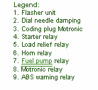
Fuse Panel Layout Diagram Parts: flasher unit, dial needle damping, coding plug motronic, starter relay, load relief relay, horn relay, fuel pump relay, motronic relay, ABS warning system.

Thursday, 12 September 2013

0 Comments
Posted in Arrangement, Art, Business

Cold Alignment Engine To GearBox

Cold Alignment Engine To GearBox

Wednesday, 11 September 2013

0 Comments
Posted in Arrangement, Art, Business

Simple Voltage to Current Converter Drives White LEDs

You sometimes need to drive a white LED from one 1.5V battery. Unfortunately, the forward voltage of a white LED is 3 to 4V. So, you would need a dc/dc converter to drive the LED from one battery. Using the simple circuit in Figure 1, you can drive one white LED or two series-connected green LEDs, using only a few components. The circuit is a voltage-to-current converter, which converts the battery voltage to a current that passes through the LED.

You can adjust this current and, thus, the brightness of the LED, by varying resistor R3. If you turn on switch S1, resistor R2 feeds base current to transistor Q2. Q2 turns on, and its collector current, via R3, turns on Q1. Now, the current through inductor L1 increases. The slope of the increase is a function of the value of L1 and the battery voltage. The current through L1 increases until it reaches a maximum value, which depends on the gain of Q1. Because the value of R3 sets the base current drawn from Q1, Q1s collector current is also limited.

White LEDs Circuit Diagram

White LEDs Circuit Diagram


Once the current through L1 reaches its maximum value, the slope of the current through L1 changes. At that instant, the voltage on L1 switches to a negative polarity forced by the changed slope. This negative voltage traverses capacitor C1 and turns off Q2, which in turn turns off Q1. The negative voltage on L1 increases until it reaches the forward voltage of the LED. The peak current through inductor L1 now flows through the LED and decreases to zero. Now, Q2 switches on again, via the current through R2, and the cycle starts again.

By adjusting resistor R3, you can set the peak current through L1 and the peak current through the LED. The brightness of an LED is a linear function of the current through the LED. So, adjusting the value of R3 also adjusts the brightness of the LED.

It doesnt matter which LED you use; the forward voltage on the LED always increases until the peak current through L1 flows through the LED. Different forward voltages of the LEDs yield different on-times (duty cycles) but the same peak current through the LED. With the values shown in Figure 1, the circuit oscillates at a frequency of approximately 30 kHz and delivers a 20-mA peak current through the LED.

The duty cycle depends on the ratio of the battery voltage to the forward voltage of the LED. One advantage of this circuit is that it requires no series-limiting resistor for the LED. The peak current through the LED is a function of the value of R3 and the gain of Q1.[via]

Tuesday, 10 September 2013

0 Comments
Posted in Arrangement, Art, Business

Simple Wireless TRIAC Dimmer

This project was used as a wireless light dimmer, but in principle can be used to dim resistive loads and wirelessly turn on/off loads. The current code includes a routine to dim a light bulb in a “heartbeat” pattern, with the heartbeat frequency remotely adjustable.


The top left of the schematic shows the wall outlet (US 120VAC) being stepped down with a small transformer, then full rectified and regulated. This powers the entire board from the wall. The top right shows a microcontroller, ATmega48, its programming header, and a UART connection to the microcontroller (for debugging). The bottom right shows the XBee and its basic voltage regulation (it’s 3.3V), as well as an LED that indicates when the XBee is connected.

Thursday, 5 September 2013

0 Comments
Posted in Arrangement, Art, Business

FM Transmitter Bug Circuit

Circuit Diagram 
Notes:
 This small transmitter uses a hartley type oscillator. Normally the capacitor in the tank circuit would connect at the base of the transistor, but at VHF the base emitter capacitance of the transistor acts as a short circuit, so in effect, it still is. The coil is four turns of 18swg wire wound around a quarter inch former. The aerial tap is about one and a half turns from the supply end. Audio sensitivity is very good when used with an ECM type microphone insert
  
Author: David, radio_david@yahoo.com
Source http://www.electronics-lab.com/

Wednesday, 4 September 2013

0 Comments
Posted in Arrangement, Art, Business

Solid State Relay Required Only 50uA Drive Current

This circuit demands a control current that is 100 times smaller than that needed by a typical optically isolated solid state relays. It is ideal for battery-powered systems. Using a combination of a high current TRIAC and a very sensitive low current SCR, the circuit can control about 600 watts of power to load while providing full isolation and transient protection.

Solid State Relay Circuit diagram:

Tuesday, 3 September 2013

0 Comments
Posted in Arrangement, Art, Business

Touch Sensor Switch Using Inverters

This touch sensor switch can is designed using inverters (N1, N2)and some common electronic components. In standby state at the entrances of N1 there is a signal produced by oscillator N3/N4. At the touch sensor hand capacity forms a bridge to the ground for the 1MHz signal so that the voltage signal at the entrance of N1 decreases more (at the exit of N2 is logical 1). After the release of contact, a signal charge C4 through D1 Mhz, so the output of N2 is 0 logic after short time.

Touch Sensor Switch Using Inverters Circuit Diagram


Installation can be powered with a DC voltage between 3 and 15 volts (maximum current of 2 mA is absorbed).

Monday, 2 September 2013

0 Comments
Posted in Arrangement, Art, Business

Subwoofer Filter and Low Pass Filter with LM741

The acoustics of converting a filter, there are many aspects of the economic viability of the more famous are baxandal filter low and high frequency filters and crossover Acoustic space is transformed into sub-domains, so that the Thursday Speakers. Applications, we offer a filter, the limits of the region to transform acoustic (20-20000Hz) in the region of 20-100Hz.

Subwoofer Filter and Low Pass Filter Circuit Diagram


The signal for a first high pass filter C1, C2, P1, which is undesirable level DC input. A lowpass filter consisting of R3, R4, C3 prevents frequencies above 10 kHz, which do not benefit from this design, and it would be that the instability and noise. The summary amp invert signal.

The low Summary of the amplifier signals go to a second low-pass filter to prevent the frequency from the speakers. I decided, a second order, as this box with a closed place feature. If you have a circuit with a valve system, and then simply close the Wind (Roll a pair of socks and pick at the port / Wind), this will give you a sealed box instead.

Sunday, 1 September 2013

0 Comments
Posted in Arrangement, Art, Business

Remote Solar LED Light

I created this circuit in an attempt to make the simplest possible solar powered project. It would make for an excellent science fair project, and would also serve as a good introduction to solar powered circuitry. It may also have some practical uses, such as shedding some light into a dark part of your house. The idea is simple, the solar panel converts sunlight into a trickle of electricity. The electricity is used to run a white LED.

 Remote Solar LED Light  Circuit Diagram


Remote Solar LED Light

Specifications:
  • Operating Voltage: 3.7V DC
  • Solar Current: 25ma max.
  • LED Lamp Operating Current: 10-25ma.
Theory:
The remote solar powered LED light takes advantage of the current limited nature of solar photovoltaic cells. If light shines on the solar array, current will flow through the circuit. For a typical size of solar cell, there is a maximum current that can be produced. The maximum solar cell current is simply matched to a value of current that the LED can handle. If there is enough light to raise the solar panels voltage above around 3.7V, the white LED will light up. The LED regulates the maximum voltage across the circuit to around 3.7V.If the solar panel that you use produces more than 20ma, it may be necessary to insert a series resistor between the LED and the solar panel to prevent the LED from burning out.

A 50 ohm 1/4 watt resistor is probably about right for the job, the exact value may need to be optimized according to the solar panel that you use.This concept could easily be expanded to systems with larger arrays of solar cells and more LEDs. The capacitor is not required, but it will keep the LED from flickering if the panel is briefly blocked, such as when a bird flies by. With 7 solar cells, the LED will only light in fairly bright light, if you use up to 10 solar cells, the circuit will work nicely in overcast skies.For an interesting modification to this circuit, replace the 1000uF capacitor with a 1 Farad/5.5V "Memory Backup Capacitor". An Elna DB-545D105 device was tested on the circuit, after charging up in the sun for a few minutes, the capacitor was able to light the LED for several minutes.

Remote Solar LED Light


Construction:
Most of the work goes into making the solar panel. Lay out the cells in any pattern. Cut the two pieces of plexiglass and one piece of perforated circuit board so that they are wider than the solar array. Stack the three board layers together and drill holes for the mounting screws. When the project is finished, the center circuit board will be spaced away from the front and back plastic panels with extra nuts acting as spacers on the mounting screws. The idea is to get an air gap above and below the circuit board so that there is room for the solar cells and wiring.

Mount the solar cells on the perf board and solder them into a series string. An easy way to do this is to connect short segments of bare wire-wrap wire to each cell, route the wires through the perf board and solder the ends on the bottom. Connect two wires to the ends of the series string of cells and secure the wires to the circuit board. For outdoor applications, seal the edge of the panel with silicone caulk or other water proof material. Also, seal the mounting screws where they pass through the plexiglass.Connect the LED and capacitor in parallel, wire them across the two power leads. Be sure to get the polarity correct, otherwise the LED wont light up. Solder the parts together. Be sure to heat-sink the LED leads while soldering, LEDs can be easily destroyed with too much heat.

Use:
Place the solar panel in the sun, the LED will light. The photo at the top of this page shows the circuit operating indoors on a cloudy day. If you put the LED on a long wire, it can be placed in a dark location, such as a corner of your basement. As long as there is a fair amount of light in the sky, the LED will light up. To get the best orientation for the panel, aim it directly at the sun at noon during March or September.

Parts:
7-10x photovoltaic cells, rated at 15-25ma each.
1x white LED, high efficiency types work best.
1x 1000uF 15V (or greater) electrolytic capacitor.
1 piece of perforated or printed circuit board.
2 pieces of clear plexiglass.
28 gauge bare wire-wrap wire.
24 gauge speaker wire.
miscellaneous screws, nuts, and washers.
silicone caulk.

    Total Pageviews