Thursday, 2 October 2014

0 Comments
Posted in Arrangement, Art, Business

Simple Triangle Square wave Oscillator Circuit Diagram

Simple triangle-square wave oscillator circuit diagram. In this circuit by making Rt variable it is possible to alter the operating frequency over a 100 to 1 range Versatile triangle/square wave oscillator has a possible frequency range of 0 Hz to 100 kHz.

Triangle Square wave Oscillator Circuit Diagram

Triangle Square wave Oscillator Circuit Diagram


Sourced By: circuitsdiagram-lab
0 Comments
Posted in Arrangement, Art, Business

LED Heart PWM Fading

The concept for this small birthday present was to create a small heart shape with red LEDs and then to draw a heart shape underneath it on the PCB as a backdrop. Then a small processor was added to control the heart shape of LEDs for both fade and pattern control. The method of control that we use (PWM) allows us to save precious battery life, control the exact brightness of each specific LED and create this tiny but awesome project. [Link]


LED Heart PWM Fading schematic
0 Comments
Posted in Arrangement, Art, Business

Long range Burglar Alarm Using Laser Torch

Laser torch-based burglar alarms normally work in darkness only. But this long-range photoelectric alarm can work reliably in daytime also to warn you against intruders in your big compounds, etc. The alarm comprises laser transmitter and receiver units, which are to be mounted on the opposite pillars of the entry gate. Whenever anyone enters to interrupt the transmitted laser beam falling on the receiver, the buzzer in the receiver circuit sounds an alarm.

The range of this burglar alarm is around 30 metres, which means you can place the transmitter and the receiver up to 30 metres apart. Since the laser torch can transmit light up to a distance of 500 metres, this range can be increased by orienting the phototransistor sensor properly. To avoid false triggering by sunlight, mount the phototransistor sensor such that it doesn’t directly face sunlight.

Long-range Burglar Alarm Using Laser Torch

Long-range Burglar Alarm Using Laser Torch


Fig. 1: Circuit of laser torch based transmitter

The transmitter circuit is powered by 3V DC. The astable multivibrator built around timer 7555 (IC1) produces 5.25kHz frequency. CMOS version of timer 7555 is used for low-voltage operation. The body of the laser torch is connected to the emitter of npn transistor T1 and the spring-loaded lead protruding from inside the torch is connected to the ground.

The receiver circuit is powered by 12V DC. It uses photoDarlington 2N5777 (T2) to sense the laser beam transmitted from the laser torch. The output beam signals from photoDarlington are given to the two-stage amplifier followed by switching circuit, etc. As long as the laser beam falls on photoDarlington T2, relay RL1 remains un-energised and the buzzer does not sound. Also, LED1 doesn’t glow.

Long-range Burglar Alarm Using Laser Torch

Long-range Burglar Alarm Using Laser Torch
 Fig. 2: Receiver circuit

When anyone interrupts the laser beam falling on photoDarlington T2, npn transistor T6 stops conducting and npn transistor T7 is driven into conduction. As a result, LED1 glows and relay RL1 energises to sound the buzzer for a few seconds (determined by the values of resistor R15 and capacitor C10). At the same time, the large indication load (230V AC alarm for louder sounds or any other device for momentary indication) also gets activated as it is connected to 230V AC mains via normally opened (N/O) contact of relay RL1.

Sourced By : EFY Author:  Pradeep G.
0 Comments
Posted in Arrangement, Art, Business

Dual Regulated Power Supply Circuit Diagram

In this Dual Regulated Power Supply Circuit Diagram, the 7815 regulates the positive supply, and the 7915 regulates the negative supply. The transformer should have a primary rating of 240/220 volts for europe, or 120 volts for North America. The centre tapped secondary coil should be rated about 18 volts at 1 amp or higher, allowing for losses in the regulator. An application for this type of circuit would be for a small regulated bench power supply. 

 Dual Regulated Power Supply Circuit Diagram

Dual Regulated Power Supply Circuit Diagram

0 Comments
Posted in Arrangement, Art, Business

Stabilized Capacitance Buffer Circuit Diagram

This is a simplest Stabilized Capacitance Buffer Circuit Diagram. In this simple circuit using Ql and Q2 constitute a simple, high-speed FET input buffer. Ql functions as a source follower, with the Q2 current source load setting the drain-source channel current. The LT1010 buffer provides output drive capability for cables or whatever load is required. Normally, this open-loop configuration would be quite drifty because there is no de feedback. 

Stabilized Capacitance Buffer Circuit Diagram

Build a Stabilized Capacitance Buffer Circuit Diagram
The LTC1052 contributes this function to stabilize the circuit. It does this by comparing the filtered circuit output to a similarly filtered version of the input signal. The amplified difference between these signals is used to set Q2`s bias, and hence Ql `s channel current. Ql `s source line ensures that the gate never forward biases, and the 2000 pF capacitor at Al provides stable loop compensation. 
The rc network in Al`s output prevents it from seeing high-speed edges coupled through Q2`s collector-base junction. A2`s output is also fed back to the shield around Ql`s gate lead, bootstrapping the circuit`s effective in_put capacitance down to less than 1 pF.  

Sourced By : Circuitsstream
0 Comments
Posted in Arrangement, Art, Business

10 Watt Audio Power Amplifier Circuit Diagram

Build 10 Watt Audio Power Amplifier Circuit
10 Watt Audio Power Amplifier Circuit Diagram
10W PA.The 10 watts power amplifier circuit by transistor describe here is an audio amplifier with output power of 10W.Used as a low frequency class AB Amplifier. Transistor has high output current and very low distortion.This 10W audio amplifier circuit diagram using Transistor is good for small room or car audio system.This circuit is a general-purpose 10W audio amplifier for moderate-power PA or modulator use in an AM transmitter.
With higher voltages and a change in bias resistors,up to 30 W can be obtained. 

Sourced by: Circuitsstream
0 Comments
Posted in Arrangement, Art, Business

Build a Inexpensive Car Protection Unit Circuit Diagram

This is a simple Inexpensive car Protection Unit Circuit Diagram. This circuit to protect car stereo, etc from pilferage that costs less and requires no adjustments in the car but a good car cover. Place the circuit at your bedside and bring the two wires from the unit to the car (parked outside your home) and connect one wire-end to the cover and the other to the ground, with both wire-ends shorted by some weight such as a brick. So outwardly the mechanism is not visible.

Circuit of car protection unit with alarm

If someone tries to remove the cover, the alarm of the circuit starts sounding to alert you. The alarm can be switched off by resetting it using switch S1.

The car protection circuit comprises two timer ICs: one for the alarm circuit (see IC2 in Fig.1) and the other to indicate that the battery has taken over as the power source (see IC3 in Fig. 2). Normally, the protector operates off AC mains and the battery takes over only when mains fail. As the battery current is not high, the battery will last long.

As long as the two wires remain shorted, transistor T1 remains cut off. When shorting is removed, transistor T1 gets forward biased and its collector voltage drops to trigger IC2 and the piezobuzzer starts sounding.


battery-takeover indicator
 battery-takeover indicator

If mains fails, the battery-takeover indicator (shown in Fig. 2 and connected to points A, B and C in Fig. 1) immediately gets triggered at pin 2 of IC3. Its high output activates the battery-operation alarm for a couple of seconds. IC1 draws power from the battery to activate the protection unit.

After setting up the unit properly and shorting both the wires, press test switch S2. If there is no fault in the circuit, the alarm will sound. Now release test switch S2 and momentarily press reset switch S1 to switch off the alarm.


Sourced By:  EFY Author : M. Venkateswaran and T.E. Parthasarathy
0 Comments
Posted in Arrangement, Art, Business

New Zip charge Quick Charger

Why you may need a zipcharge quick charger? With so many devices around these days, making sure they have enough juice to run on is essential wherever we go. The Zipcharge Quick Charger aims to help you out with that, where it comes in the form of a rechargeable power stick that takes a mere 15 minutes of charging to provide your iPod with another 20 hours of audio playback, while you get 10 more hours of talk time.

Now, these are all theoretical figures, so you might want to take it with a pinch of salt. How about a 60 second charge that offers 2 hours of playback on your iPod?

Charging the sleek ZipCharge for a paltry 15 minutes will store enough oomph to give your iPod an extra 20 hours of playtime or your mobile phone an additional 10 hours of talk time. If you’re in a pant-trippingly awful rush, a 60 second charge whooshes in sufficient juice to power an iPod for 2 hours, a mobile phone for 8 hours, 2 Way Radio for 1 hour 20 mins or a camera for 80 photos.

zipcharge charger
So how does it work? Not being particularly spammy of head, we’re not entirely sure, but it’s got something to do with clever nano physics and cutting edge battery chemistry. But who cares about spoddy tech nonsense? The ZipCharge is set to revolutionise your gidgity gadgety life. And that’s not empty flannel because it’s brought to you by Freeplay, the game-changing boffins behind the world’s first wind-up radio. link

zipcharge quick charger

0 Comments
Posted in Arrangement, Art, Business

Simple High Power Triac Dimmable LED Driver

A 20 Watt Triac dimmable LED driver. This is basically a current controlled step-down switching power supply. The circuit is powered directly from mains so be careful with this one.

Saturday, 11 January 2014

0 Comments
Posted in Arrangement, Art, Business

Constructing your own Dual Power Supply Rise

Many times the hobbyist desires to have a simple, dual power supply for a project. Existing power supplies may be large either in power output or physical size. a simple Dual Power Supply is necessary.For most non-critical applications the best & simplest choice for a voltage regulator is the 3-terminal type.The three terminals are input, ground & output.

The 78xx & 79xx series can provide up to 1A load current & it have on chip circuitry to prevent damage in the event of over heating or excessive current. That is, the chip basically shuts down than blowing out. These regulators are cheap, simple to make use of, & they make it practical to design a method with plenty of P C Bs in which an unregulated supply is brought in & regulation is done locally on each circuit board.

This Dual Power Supply project provides a dual power supply. With the appropriate choice of transformer & 3-terminal voltage regulator pairs you can basically build a tiny power supply delivering up to amp at +/- 5V, +/- 9V, +/- 12V, +/-15V or +/-18V. You require to provide the middle tapped transformer and the 3-terminal pair of regulators you require:7805 & 7905, 7809 & 7909, 7812 & 7912, 7815 & 7915or 7818 & 7918.

The user must pick the pair they needs for his particular application.

Note that the + & - regulators do not must be matched: you can for example, use a +5v & -9V pair. However,the positive regulator must be a 78xx regulator, & the negative a 79xx. They have built in plenty of safety in to this project so it ought to give plenty of years of continuous service.

Transformer
This Dual Power Supply design makes use of a full wave bridge rectifier coupled with a centre-tapped transformer. A transformer with a power output rated at at least 7VA ought to be used. The 7VA rating means that the maximum current which can be delivered without overheating will be around 390mA for the 9V+9V tap; 290mA for the 12V+12V and 230mA for the 15V+15V. If the transformer is rated by output RMS-current then the worth ought to be divided by one.2 to get the current which can be supplied. For example, in this case a 1A RMS can deliver 1/(one.2) or 830mA.

Rectifier
They use an epoxy-packaged four amp bridge rectifier with at least a peak reverse voltage of 200V. (Note the part numbers of bridge rectifiers are not standardised so the number are different from different manufacturers.) For safety the diode voltage rating ought to be at least to times that of the transformers secondary voltage. The current rating of the diodes ought to be two times the maximum load current that will be drawn.

Filter Capacitor
The purpose of the filter capacitor is to smooth out the ripple in the rectified AC voltage. Theres dual amount of ripple is determined by the worth of the filer capacitor: the larger the worth the smaller the ripple.The two,200uF is an appropriate value for all the voltages generated using this project. The other consideration in choosing the correct capacitor is its voltage rating. The working voltage of the capacitor has to be greater than the peak output voltage of the rectifier. For an 18V supply the peak output voltage is one.4 x 18V, or 25V. So they have selected a 35V rated capacitor.

Regulators
The unregulated input voltage must always be higher than the regulators output voltage by at least 3V in order for it to work. If the input/output voltage difference is greater than 3V then the excess potential must be dissipated as heat. Without a heat sink three terminal regulators can dissipate about two watts. A simple calculation of the voltage differential times the current drawn will give the watts to be dissipated. Over two watts a heat sink must be provided. If not then the regulator will automatically turn off if the internal temperature reaches 150oC. For safety it is always best to make use of a small heat sink even in case you do not think you will need.

Stability
C4 & C5 improve the regulators ability to react to sudden changes in load current & to prevent uncontrolled oscillations.

Decoupling
The mono block capacitor C2 & C6 across the output provides high frequency decoupling which keep the impedance low at high frequencies.

LED
Two LEDs are provided to show when the output regulated power is online. You do not must make use of the LEDs in the event you do not require to. However, the LED on the negative side of the circuit does provide a maximum load to the 79xx regulator which they found necessary in the coursework of testing. The negative 3-pin regulators did not like a zero load situation. They have provided a 470R/0.5W resistors as the current limiting resistors for the LEDs.

Diode Protection
These protect chiefly against any back emf which may come back in to the power supply when it supplies power to inductive lots. They also provide additional short circuit protection in the case that the positive output is connected by accident to the negative output. If this happened the usual current limiting shutdown in each regulator may not work as intended. The diodes will short circuit in this case & protect the two regulators.

Dual Power Supply Schematic Diagram


Dual Power Supply Schematic Diagram

Friday, 10 January 2014

0 Comments
Posted in Arrangement, Art, Business

220 Volts Flashing Lamps

Especially designed for Christmas tree lamps Replaces old thermally-activated switches

This circuit is intended as a reliable replacement to thermally-activated switches used for Christmas tree lamp-flashing. The device formed by Q1, Q2 and related resistors triggers the SCR. Timing is provided by R1,R2 & C1. To change flashing frequency dont modify R1 and R2 values: set C1 value from 100 to 2200µF instead.

Circuit diagram :

lamp Circuit diagram

220 Volts Flashing Lamps Circuit Diagram

Best performances are obtained with C1=470 or 1000µF and R4=12K or 10K. Due to low consumption of normal 10 or 20 lamp series-loops intended for Christmas trees (60mA @ 220V typical for a 20 lamp series-loop), very small and cheap SCR devices can be used, e.g. C106D1 (400V 3.2A) or TICP106D (400V 2A), this last and the suggested P0102D devices having TO92 case.

Parts List:

R1 100K 1/4W Resistor
R2,R5 1K 1/4W Resistors
R3,R6 470R 1/4W Resistors
R4 12K 1/4W Resistor
C1 1000µF 25V Electrolytic Capacitor
D1-D4 1N4007 1000V 1A Diodes
D5 P0102D 400V 800mA SCR
Q1 BC327 45V 800mA PNP Transistor
Q2 BC337 45V 800mA NPN Transistor
PL1 Male Mains plug
SK1 Female Mains socket

Note:

For proper operation its absolutely necessary to employ high Gate-sensitive SCRs.

If you are unable to find these devices you can use Triacs instead. In this case the circuit operates also with relatively powerful devices. A recommended Triac type is the ubiquitous TIC206M (600V 4A) but many others can work.Note that in spite of the Triac, diode bridge D1-D4 is in any case necessary.

This circuit was awarded with publication in ELECTRONICS WORLD "Circuit Ideas", June 2000 issue, page 458

0 Comments
Posted in Arrangement, Art, Business

Loudspeaker Protector Monitors Current

This circuit uses a 0.1O 1W resistor connected in series with the output of a power amplifier. When the amplifier is delivering 100W into an 8O load, the resistor will be dissipating 1.25W. The resulting temperature rise is sensed by a thermistor which is thermally bonded to the resistor. The thermistor is connected in series with a resistor string which is monitored by the non-inverting (+) inputs of four comparators in an LM339 quad comparator.

All of the comparator inverting inputs are connected to an adjustable threshold voltage provided by trimpot VR1. As the thermistor heats up, its resistance increases, raising the voltage along the resistor ladder.

Circuit diagram:
Loudspeaker protector monitors current circuit schematic
Loudspeaker Protector Circuit Diagram

When the voltage on the non-inverting input of each comparator exceeds the voltage at its inverting input, the output switches high and illuminates the relevant LED. NOR gate latches are connected to the outputs of the third and fourth comparators. When the third comparator switches high, the first latch is set, turning on Q1 and relay 1. This switches in an attenuation network (resistors RA & RB) to reduce the power level.

However, if the power level is still excessive, comparator 4 will switch, setting its latch and turning on Q2 and relay 2. This disconnects the loudspeaker load. The thermistor then needs to cool down before normal operation will be restored. The values of R1-R4 depend on the thermistor used. For example, if a thermistor with a resistance of 1.5kO at 25°C is used, then R1 could be around 1.5kO and R2, R3 and R4 would each be 100O (depending the temperature coefficient of the thermistor).

The setup procedure involves connecting a sinewave oscillator to the input of the power amplifier and using a dummy load for the output. Set the power level desired and adjust trimpot VR1 to light LED1. Then increase the power to check that the other LEDs light at satisfactory levels.

Author: David Devers - Copyright: Silicon Chip Electronics

Thursday, 9 January 2014

0 Comments
Posted in Arrangement, Art, Business

Ultrasonic Dog Whistle

Its well known that many animals are particularly sensitive to high-frequency sounds that humans cant hear. Many commercial pest repellers based on this principle are available, most of them operating in the range of 30 to 50 kHz. My aim was, however, to design a slightly different and somewhat more powerful audio frequency/ultrasonic sound generator that could be used to train dogs. Just imagine the possibilities - you could make your pet think twice before barking again in the middle of the night or even subdue hostile dogs (and I guess burglars would love that!).

From what Ive read, dogs and other mammals of similar size behave much differently than insects. They tend to respond best to frequencies between 15 and 25 kHz and the older ones are less susceptible to higher tones. This means that an ordinary pest repeller wont work simply because dogs cant hear it. Therefore, I decided to construct a new circuit (based on the venerable 555, of course) with a variable pitch and a relatively loud 82 dB miniature piezo beeper.

The circuit is very simple and can be easily assembled in half an hour. Most of the components are not really critical, but you should keep in mind that other values will probably change the operating frequency. Potentiometer determines the pitch: higher resistance means lower frequency. Since different dogs react to different frequencies, youll probably have to experiment a bit to get the most out of this tiny circuit. The circuit is shown below:

Ultrasonic Dog Whistle Circuit diagram


Despite the simplicity of the circuit, there is one little thing. The 10nF (.01) capacitor is critical as it, too, determines the frequency. Most ceramic caps are highly unstable and 20% tolerance is not unusual at all. Higher capacitance means lower frequency and vice-versa. For proper alignment and adjustment, an oscilloscope would be necessary. Since I dont have one, I used Winscope. Although its limited to only 22 kHz, thats just enough to see how this circuit works.

There is no need to etch a PCB for this project, perf board will do. Test the circuit to see how it responds at different frequencies. A 4k7 potentiometer in conjunction with a 10nF (or slightly bigger) capacitor gives some 11 to 22kHz, which should do just fine. Install the circuit in a small plastic box and if you want to, you can add a LED pilot light. Power consumption is very small and a 9V battery should last a long time. Possible further experimentation:

 Im working on an amplified version of the whistle to get a louder beep. All attempts so far havent been successful as high frequency performance tends to drop dramatically with the 555. Perhaps I could use a frequency doubler circuit - I just dont know and Ive run out of ideas. One other slightly more advanced project could be a simple "anti-bark" device with a sound-triggered (clap) switch that sets off the ultrasonic buzzer as soon as your dog starts to bark.
0 Comments
Posted in Arrangement, Art, Business

Build a Digital Electronic Lock Circuit Diagram

This Digital Electronic Lock Circuit Diagram shown below uses 4 common logic ICs to allow controlling a relay by entering a 4 digit number on a keypad. The first 4 outputs from the CD4017 decade counter (pins 3,2,4,7) are gated together with 4 digits from a keypad so that as the keys are depressed in the correct order, the counter will advance. As each correct key is pressed, a low level appears at the output of the dual NAND gate producing a high level at the output of the 8 input NAND at pin 13.

Read : Cheap Bicycle Alarm Schematics Circuit

Digital Electronic Lock Circuit Diagram

Digital Electronic Lock Circuit Diagram
 

The momentary high level from pin 13 activates a one shot circuit which applies an approximate 80 millisecond positive going pulse to the clock line (pin 14) of the decade counter which advances it one count on the rising edge.

Read : Emergency Light and Alarm Circuit Diagram

A second monostable, one shot circuit is used to generate an approximate 40 millisecond positive going pulse which is applied to the common point of the keypad so that the appropriate NAND gate will see two logic high levels when the correct key is pressed (one from the counter and the other from the key). The inverted clock pulse (negative going) at pin 12 of the 74C14 and the positive going keypad pulse at pin 6 are gated together using two diodes as an AND gate (shown in lower right corner).

Read : Burglar Alarm With Timed Shutoff Circuit Diagram

The output at the junction of the diodes will be positive in the event a wrong key is pressed and will reset the counter. When a correct key is pressed, outputs will be present from both monostable circuits (clock and keypad) causing the reset line to remain low and allowing the counter to advance. However, since the keypad pulse begins slightly before the clock, a 0.1uF capacitor is connected to the reset line to delay the reset until the inverted clock arrives.

Read : 5 Zone alarm Circuit Diagram

The values are not critical and various other timing schemes could be used but the clock signal should be slightly longer than the keypad pulse so that the clock signal can mask out the keypad and avoid resetting the counter in the event the clock pulse ends before the keypad pulse. The fifth output of the counter is on pin 10, so that after four correct key entries have been made, pin 10 will move to a high level and can be used to activate a relay, illuminate an LED, ect. At this point, the lock can be reset simply by pressing any key. The circuit can be extended with additional gates (one more CD4011) to accept up to a 8 digit code.

Read :  Alarm Control Keypad Circuit Diagram

The 4017 counting order is 3 2 4 7 10 1 5 6 9 11 so that the first 8 outputs are connected to the NAND gates and pin 9 would be used to drive the relay or light. The 4 additional NAND gate outputs would connect to the 4 remaining inputs of the CD4068 (pins 9,10,11,12). The circuit will operate from 3 to 12 volts on 4000 series CMOS but only 6 volts or less if 74HC parts are used. The circuit draws very little current (about 165 microamps) so it could be powered for several months on 4 AA batteries assuming only intermittent use of the relay.

Friday, 27 December 2013

0 Comments
Posted in Arrangement, Art, Business

PC Heat Monitor

The PC processor generates very high temperature during its operation which is dissipated by the large heat sink placed above the processor. If the heat sink assembly is not tight with the processor or the cooling fan is not working, PC enters into the Thermal shutdown mode and will not boot up. If the PC is not entering into thermal shutdown, the high temperature can destroy the processor. This simple circuit can be placed inside the PC to monitor the temperature near the processor. It gives warning beeps when the temperature near the heat sink increases abnormally. This helps to shutdown the PC immediately before it enters into Thermal shutdown.

Circuit Project: PC Heat Monitor Circuit 

The circuit uses a Piezo element (one used in Buzzer) as the heat sensor. The piezo crystals reorient when subjected to heat or mechanical stress and generates about one volt through the Direct piezoelectric property. IC1 is designed as a voltage sensor with both the inputs tied through the capacitor C1.The non inverting input is connected to the ground through R1 to keep the output low in the standby state. The inputs of IC1 are very sensitive and even a minute change in voltage level will change the output state.

Circuit Project: PC Heat Monitor Circuit

In the standby mode, both the inputs of IC1 are balanced so that output remains low. When the Piezo element accepts heat, it generates a minute voltage which will upset the input balance and output swings high. This triggers LED and Buzzer. Capacitor C2 gives a short lag before the buzzer beeps to avoid false triggering. Warning beep continues till the piezo element cools.

Note: Enclose the circuit inside the PC with the piezo element close to the heat sink of the processor. Adjust the distance between the piezo element and heat sink so as to keep the circuit standby in the normal condition. The piezo element can sense a 10 degree rise in temperature from a distance of 5 cms. Power to the circuit can be tapped from the 12 volt line of SMPS.

Thursday, 26 December 2013

0 Comments
Posted in Arrangement, Art, Business

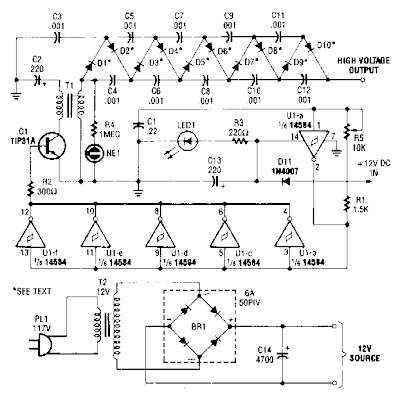
High Voltage DC Generator Circuit Diagram

This circuit is fed from a 12-V de power supply. The input to the circuit is then amplified to provide a 10,000-Vdc output. The output of the up-converter is then fed into a 10 stage, high-voltage multiplier to produce an output of 10,000 Vdc.


High Voltage DC Generator Circuit Diagram

High Voltage DC Generator Circuit Diagram

Wednesday, 25 December 2013

0 Comments
Posted in Arrangement, Art, Business

7805 Voltage Regulator Circuit

A voltage regulator is used to produce a constant linear output voltage. It’s generally used with AC to DC power supply. And also it can be used as well as a DC to DC voltage converter . To regulating low voltage, most used device is one single IC. 7805, 7812, 7905 etc. 78xx series are design for positive and 79xx series are for Negative voltage regulator.

7805 is a three terminal +5v voltage regulator IC from 78XX chips family. See 7805 pinout below. LM78XX series are from National Semiconductor. They are linear positive voltage regulator IC; used to produce a fixed linear stable output voltage.  National Semiconductor has also negative voltage regulator chips family, they indicate with LM 79XX. 78xx is used more than 79xx because negative voltage has a few usability purposes as we see.
I was previously posted a 5v regulated power supply circuit using 7805 IC, that circuit and this 7805 voltage regulator circuit is almost the same.


Circuit diagram of 7805 Voltage Regulator


Fig: 7805 Voltage Regulator Circuit


7805 pinout


7805 pinout, pin diagram
Fig: Pinout of 7805

Its output voltage is +5V DC that we need. You can supply any voltage in input; the output voltage will be always regulated +5V. But my recommendation is, don’t supply more than 18V or less than 8V in input. There used two capacitors in this voltage regulator circuit, they aren’t mandatory to use. But it will be best if you use them. They helped to produce a smooth regulated voltage at output. Use electrolyte capacitor instead of ceramic capacitor.

One limitation of 7805 I have found that is its output current 1A maximum. Otherwise it is a good voltage regulator if you are happy with 1A. But if   you need over 400mA current in output then you should use a Heat Sink with IC LM7805. Otherwise it may fall damage for overheating.

Tuesday, 24 December 2013

0 Comments
Posted in Arrangement, Art, Business

Pre regulated High Voltage Power Supply Circuit Diagram

This Pre-regulated High Voltage Power Supply Circuit Diagram triacs selects the tap on main transformer Tl, which provides the proper, pre-regulated voltage to the secondary regulator. T2 and its associated components comprise the secondary regulator. The ADC 0804, IC1, digitizes a voltage-feedback signal from the secondary regulator`s output. 

 Pre-regulated High Voltage Power Supply Circuit Diagram

Pre-regulated High Voltage Power Supply Circuit Diagram


The MC1415 De-multiplexer, IC2, decodes the digitizer`s output. IC2, in turn, drives Tl`s opto-isolated triacs via the 74LS240 driver chip, IC3, and associated opto-isolators. Transformer T3 samples the circuit`s current output. The auxiliary, 12 V winding on Tl ensures noload starting. The combination of op amp IC5 and the inverting transistor, Ql, square this current signal. 

The output of Ql is the CLK signal, which triggers one-half of the one shot, IC4A, to begin the circuit`s AID conversion. The one shots` periods are set to time out within 1l2 cycle of the ac input. Upon completion of its AID conversion, ICl`s INTR output triggers the other half of the one shot, IC4B, which enables the converter`s data outputs. The rising edge of the CLK signal resets the one shot and latches the new conversion value into IC2. The latch, associated driver, and optoisolator trigger a selected triac according to the latest value of the voltage-feedback signal, V, . Keep enjoying dont forget click on share button .


Monday, 23 December 2013

0 Comments
Posted in Arrangement, Art, Business

Mobile Car Stereo Player

Using a mobile phone while driving is dangerous. It is also against the law. However, you can use your mobile phone as a powerful music player with the help of a stereo power amplifier. This does away with the need of a sophisticated in-dash car music system. Most mobile phones have a music player that offers a number of features including preset/manual sound equalisers. They have standard 3.5mm stereo sockets that allow music to be played through standard stereo headphones/sound amplifiers. Nokia 2700 classic is an example.

Mobile Car Stereo Player Circuit Diagram

Circuit of mobile car stereo player

A car audio amplifier with 3.5mm socket can be designed and simply connected to the mobile phone output via a shielded cable with suitable connectors/jacks (readymade 3.5mm male-to-male connector cable is a good alternative). Fig. 1 shows the circuit of car stereo player. It is built around popular single-chip audio power amplifier TDA1554Q (IC1). The TDA1554Q is an integrated class-B power amplifier in a 17-lead single-in-line (SIL) plastic power package.

IC TDA1554Q contains four 11W identical amplifiers with differential input stages (two inverting and two non-inverting) and can be used for single-ended or bridge applications. The gain of each amplifier is fixed at 20 dB. Here it is configured as two 22W stereo bridge amplifiers. The amplifier is powered from the 12V car battery through RCA socket J2. Diode D1 protects against wrong-polarity connection. LED1 indicates the power status.

Stereo Jack :
3.5mm stereo socket and (b) 3.5mm

(a) 3.5mm stereo socket and (b) 3.5mm Stereo Jack

Connect stereo sound signal from the 3.5mm headset socket of the mobile phone to audio input socket J1. When you play the music from your mobile, IC1 amplifies the input. The output of IC1 is fed to speakers LS1 and LS2 fitted at a suitable place in your car. Electrolytic capacitor C5 connected between pin 4 of IC1 and GND improves the supply-voltage ripple rejection. Components R2 and C4 connected at mute/standby pin (pin 14) of IC1 eliminate the switch on/off plop. The circuit is quite compact. A good-quality heat-sink assembly is crucial for IC1. Fig. 2 shows the stereo socket and stereo jack.

Proposed enclosure
Proposed enclosure

Assemble the circuit on a general-purpose PCB and enclose in a suitable cabinet. Small dimensions of the power amplifier make it suitable for being enclosed in a plastic (ABS) case with vent holes. Signal input socket, speaker output terminals, on/off switch, indicator, fuse holder and power supply socket are best located on the front panel of the enclosure as shown in Fig. 3.

Source : http://www.ecircuitslab.com/2012/04/mobile-car-stereo-player.html

Sunday, 22 December 2013

0 Comments
Posted in Arrangement, Art, Business

best cell phone jammer will stop working immediately

The over heat of best cell phone jammer should be timely dissipated.
Chinas mobile advertising does not scale, but it must embark on the road and internet advertising, but more business model remains to be explored. Several models of mobile media advertising. In China, mobile media advertising model can be divided into the following categories: the earliest provider of wireless advertising professional Focus wireless, using this model. There are two specific advertising: Point report, and direct report. Point report, through the identification of the users identity with the aid of technical means to fully tap the user attributes, automatically match the user properties to cater to user preferences ads to the users see on the page, different people see different ads precise The sentinel marketing. And get these best cell phone jammer directly from the supplier in the a shorter time.
Difficult to sell to a pack of cigarettes a woman, though she had the purchasing power, but she did not need, when you pass her cigarette advertising, is still spam. In other words, no will to produce spam, that is the wrong content delivery to the wrong object, although the advertising arrival rate, but not the demand, the result is still negative. SMS group sending, are examples. Win-win is the last word. The future of mobile advertising is first and foremost to be able to obtain permission from the customer, in other words, the ad itself is a value-added behavior for the audience, you can achieve a win-win of the advertisers and the audience will never users interfere. The inspection of some other wireless signals can be carried out by best cell phone jammer .
Type of mobile advertising is popular. Through a series of positioning and data analysis, cell text messaging information targeted to send to give advertising related to the user, for example, passengers waiting at the airport will often receive a discount ticket information. Business services, exhibition, hotel, shopping malls, automobile, FMCG, banking, real estate and other industries are beginning to Cell SMS platform to launch mobile advertising. "Mobile advertising mobile marketing is the next step." Communication University of China Vice-Chancellor Ding Junjie, "However, the main problems facing the mobile advertising is still lack a lot of professional standards, such as results-based monitoring of mobile advertising standards, the standard of the quotation system, advertising reach the standard of the cost of thousands of users and so on. And at the same time best cell phone jammer will stop working immediately.
Internet users are mainly concentrated in the eastern coastal areas and some inland provinces.

    Total Pageviews