Showing posts with label alarm. Show all posts

Thursday, 2 October 2014

0 Comments
Posted in Arrangement, Art, Business

Long range Burglar Alarm Using Laser Torch

Laser torch-based burglar alarms normally work in darkness only. But this long-range photoelectric alarm can work reliably in daytime also to warn you against intruders in your big compounds, etc. The alarm comprises laser transmitter and receiver units, which are to be mounted on the opposite pillars of the entry gate. Whenever anyone enters to interrupt the transmitted laser beam falling on the receiver, the buzzer in the receiver circuit sounds an alarm.

The range of this burglar alarm is around 30 metres, which means you can place the transmitter and the receiver up to 30 metres apart. Since the laser torch can transmit light up to a distance of 500 metres, this range can be increased by orienting the phototransistor sensor properly. To avoid false triggering by sunlight, mount the phototransistor sensor such that it doesn’t directly face sunlight.

Long-range Burglar Alarm Using Laser Torch

Long-range Burglar Alarm Using Laser Torch


Fig. 1: Circuit of laser torch based transmitter

The transmitter circuit is powered by 3V DC. The astable multivibrator built around timer 7555 (IC1) produces 5.25kHz frequency. CMOS version of timer 7555 is used for low-voltage operation. The body of the laser torch is connected to the emitter of npn transistor T1 and the spring-loaded lead protruding from inside the torch is connected to the ground.

The receiver circuit is powered by 12V DC. It uses photoDarlington 2N5777 (T2) to sense the laser beam transmitted from the laser torch. The output beam signals from photoDarlington are given to the two-stage amplifier followed by switching circuit, etc. As long as the laser beam falls on photoDarlington T2, relay RL1 remains un-energised and the buzzer does not sound. Also, LED1 doesn’t glow.

Long-range Burglar Alarm Using Laser Torch

Long-range Burglar Alarm Using Laser Torch
 Fig. 2: Receiver circuit

When anyone interrupts the laser beam falling on photoDarlington T2, npn transistor T6 stops conducting and npn transistor T7 is driven into conduction. As a result, LED1 glows and relay RL1 energises to sound the buzzer for a few seconds (determined by the values of resistor R15 and capacitor C10). At the same time, the large indication load (230V AC alarm for louder sounds or any other device for momentary indication) also gets activated as it is connected to 230V AC mains via normally opened (N/O) contact of relay RL1.

Sourced By : EFY Author:  Pradeep G.

Thursday, 19 December 2013

0 Comments
Posted in Arrangement, Art, Business

THIEF ALARM WITHOUT IC NE555


THIEF ALARM (WITHOUT IC NE555)
INDRODUCTION:-
This is the easiest way to make a thief alarm. If you know how to make an ordinary electric circuit, this circuit would be very simple than the other method.
MATERIALS REQUIRED:-
11)      Breadboard                                               1
22)      12v/230v Transformer                                1(2)
33)      Buzzer                                                        1
44)      LED                                                           4
55)      LDR(RESISTANCE IN DARKNESS       1
66)      Resistor 48 K Ohms                                   2
77)      Resistor 100 ohms                                      2
PROCEDURE:-  
Take the breadboard and connect the 12v/230v transformer to the pin numbers 5 and 10.connect the 100 ohms resistors to the pins 1b and 5b.Then connect one wire of the transformer directly to the resistors 48 k ohms leading to the +ve terminals of the buzzer and the LED. Then connect the next wire of the transformer to the LDR’s first terminal then connect the next terminal of the LDR to the –ve terminals of the buzzer and LED. Now switch off the light.When the intruder switches on his torch the
                                Circuit
    

Wednesday, 14 August 2013

0 Comments
Posted in Arrangement, Art, Business

Simple Light Sensor Alarm circuit with NE555

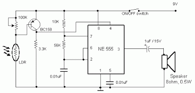
Occurring this circuit sent out an alarm when its LDR sensor is exposed to light by sun or lamp. A 555 stable multivariate was used here which sent signal a tone of about 1kHz upon detecting light.The sensor when exposed by light completes the circuit and makes the 555 oscillate at about 1kHz with transistor to drive current.

The sensor is also shown in the circuit diagram. It has to placed making an angle of about 30 – 45 degrees to the ground.

 Light Sensor Alarm circuit with NE555
 Sensitivity can be adjust with P1.
 This makes the sun light to flow through it to the ground and prevents the alarm from going on due to the stored light on the sensor

Friday, 12 April 2013

0 Comments
Posted in Arrangement, Art, Business

Simple Light Sensor Alarm circuit with NE555

Occurring this circuit despatched out an alarm when its LDR sensor is exposed to gentle by way of solar or lamp. A 555 steady multivariate used to be used here which sent sign a tone of about 1kHz upon detecting mild.The sensor when uncovered by mild fulls the circuit and makes the 555 oscillate at about 1kHz with transistor to pressure current.

The sensor can be shown within the circuit diagram. It has to placed making an angle of about 30 – forty five degrees to the bottom.

 Sensitivity will additionally be regulate with P1.
 This makes the solar gentle to drift via it to the bottom and stops the alarm from happening as a outcome of the saved mild on the sensor

Tuesday, 9 April 2013

0 Comments
Posted in Arrangement, Art, Business

Touch Door Alarm Circuit Using 555 Timer IC

This is a design simple alarm that can be used to provide a audible alarm when someone touches the door knob or handle of your room. The door knob or handle must be made of metal for the circuit to work. The main chip in the circuit is a 555 timer which will be triggered if a hand comes close to or touches the door knob.


The circuit attaches to the door knob at the end of the 1 Mega ohm resistor. This is operation of the circuit. Once the timer is triggered the LED will light and the UJT will output a tone to the speaker. The timers will time out in 5 seconds. The sensitivity of the trigger can be changed by changing the 1 Mega ohm resistor to another value. The 5 second time out can be adjusted by changing the value of the resistor connected between pin 8 and pin 7. The output tone can be changed by changing the RC values on the base of the UJT.

    Total Pageviews