Showing posts with label amplifier. Show all posts

Thursday, 2 October 2014

0 Comments
Posted in Arrangement, Art, Business

10 Watt Audio Power Amplifier Circuit Diagram

Build 10 Watt Audio Power Amplifier Circuit
10 Watt Audio Power Amplifier Circuit Diagram
10W PA.The 10 watts power amplifier circuit by transistor describe here is an audio amplifier with output power of 10W.Used as a low frequency class AB Amplifier. Transistor has high output current and very low distortion.This 10W audio amplifier circuit diagram using Transistor is good for small room or car audio system.This circuit is a general-purpose 10W audio amplifier for moderate-power PA or modulator use in an AM transmitter.
With higher voltages and a change in bias resistors,up to 30 W can be obtained. 

Sourced by: Circuitsstream

Thursday, 15 August 2013

0 Comments
Posted in Arrangement, Art, Business

170W power amplifier LM4651 and LM4652

170 Watt power amplifier is a power amplifier that is built by IC LM4651 and LM4652.


Part of this power amplifier driver using the LM4651 IC designed specifically for the purpose of the class AB amplifier driver with short circuit protection feature, containing under voltage, thermal shutdown protection and standby functions. Section 170 Watt power amplifier using LM4651 IC with a MOSFET power amplifier is equipped with temperature sensors that will be used by IC LM4651 as controlnya thermal signal. IC IC LM4651 and LM4652 are designed specifically to each other in pairs to create a class AB power amplifier with protection features are detailed. Detailed series of 170 Watt power amplifier can be seen in thethe following figure .

170W power amplifier LM4651 and LM4652

Power amplifier circuit requires supply voltages +22 V DC symmetrical 0-22V. Power Amplifier with IC LM4651 and LM4652 are often used in portable HiFi systems such as powered speakers, power subwoofer and car audio power Booter. D1, D2, D3 and D4 in series 170 watt power amplifier with LM4651 and LM4652 is a 22V zener diode.

Sunday, 4 August 2013

0 Comments
Posted in Arrangement, Art, Business

TA8210AH car audio amplifier circuit

TA8210AH 200W car amplifier schematic
IC TA8210AH By using this you can apply a series of audio power amplifier is the car audio system. In general, all the speakers in the car using a subwoofer speaker, and woofer. Because the car is not big room so the sound is being required is not too high.


Audio amplifier circuit can work at a minimum voltage 12-volt DC, if supplied under voltage 12-volt amplifier work will be less than the maximum. This amplifier output power up to 200W or 2 x 100W stereo with 8 ohm impedance.

200W car amplifier schematic

Part List :

Resistor
R1 =1K
R2 =50K trim
R3 =1K
R4 =50K trim
R5 =680R
R6 =680R
R7 =150K
R8 =2R2
R9 =2R2
R10=2R2
R11=2R2

Capacitor
C1 =1uF
C2 =1uF
C3 =47uF
C4 =47uF
C5 =100n/400V
C6 =220uF
C7 =220uF
C8 =100n/400V
C9 =100n/400V
C10=100n/400V

Intregated Circuit
IC1=TA8210AH

Connector
X2-3=in R
X2-2=gnd
X2-1=in L
X1-1,X1-2=Out R
X1-3,X1-4=Out L

Saturday, 13 April 2013

0 Comments
Posted in Arrangement, Art, Business

Power Supply for Power Amplifier 200Watt By STK4050

STK 4050 - 200Watt Power Amplifier
Amplifier circuit with IC STK is tough and good quality. In this article an amplifier circuit with IC STK another base. Power "Amplifier 200Watt By STK4050" is an audio amplifier of the STK family with 200Watt power.Power Amplifier With this STK4050 can reproduce the power 200 Watts at 8 Ohm load spaker. In making Power Amplifier 200Watt With this STK4050 do not forget to provide adequate heat sink for the IC STK 4050 in order to avoid overheating.

Schematics Amplifier STK4050-STK4046

PCB Layout Amplifier

Series Power Supply for Power Amplifier 200Watt By STK4050 been displayed in one image with a series of "Power Amplifier" 200Watt With STK4050 above. IC STK 4050 in this series there are several types on the market including STK4050II, STK4050V and STK4050.


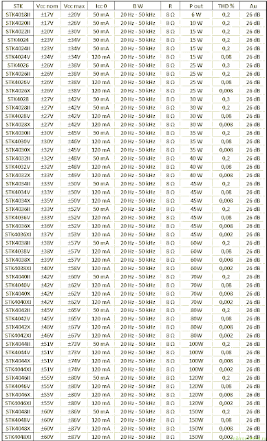
And below is a list of STK ICs are used for a good quality amplifier.

Datasheet STK IC Amplifier

Friday, 12 April 2013

0 Comments
Posted in Arrangement, Art, Business

14W CLASS A AMPLIFIER CIRCUIT USING 2N3055 SCHEMATIC DIAGRAM

14W CLASS A AMPLIFIER CIRCUIT USING 2N3055 SCHEMATIC DIAGRAM

Many early amplifiers operated in Class A, but as output powers rose above 10W the problems of heat dissipation and power supply design caused most manufacturers to turn to the simpler, more efficient Class B arrangements and to put up with the resulting drop in perceived output quality. Why Class A ? Because , when biased to class A, the transistors are always turned on, always ready to respond instantaneously to an input signal. Class B and Class AB output stages require a microsecond or more to turn on. The Class A operation permits cleaner operation under the high-current slewing conditions that occur when transient audio signal are fed difficult loads. His amplifier is basically simple, as can be seen from the block diagram.


Thursday, 11 April 2013

0 Comments
Posted in Arrangement, Art, Business

3 VOLT 6 VOLT MINI AUDIO AMPLIFIER SCHEMATIC DIAGRAM

3 VOLT - 6 VOLT MINI AUDIO AMPLIFIER SCHEMATIC DIAGRAM


The potentiometer circuit can be used to control volume. Capacitor C1 and C2 are designed to filter supplyvoltage If the battery separator is used as operations offer source.For using batteries C1 and C2 are not required.


IC TDA7052 is a mono output amplifier in 8-comng Head DI package (DIP). The device is designed primarily for battery-operated portable audio circuits. Features include TDA 7052, no external components needed, no switch-on or switch-off button sounds great overall stability and very low power consumption (quiescent current of 4 mA), low THD, it is not necessary any cooler and short-circuit proof.


Profit TDA 7052 is set internally at 40 dB. . Compensate for the reduction of output power due to low voltage TDA7052 uses Bridge-Tied-Load principle

(BTL), which can provide power about 1 to 2 W RMS (THD = 10%), 8 ohm load to the power supply 6 V.


0 Comments
Posted in Arrangement, Art, Business

150W BRIBGE AMPLIFIER WITH TDA 7294 CIRCUIT DIAGRAM

150W BRIBGE AMPLIFIER WITH TDA 7294 CIRCUIT DIAGRAM

As you can see, there are provisions to use TDA7294 well. This circuit is almost identical, but a specification higher. There are links on the board to connect contacts 1 and 5 (it should not be connected to the TDA727). Use TDA7294, fees can run bridged (BTL or bridge tied load) to about 150 W at 8 ohms. I think P87B be used to provide phase signal is necessary for BTL operation. Although it is common to see AMP as a reversal, there is a very low resistance at first, and may lead to unacceptable pressures and possible distortion. P87B be managed separately by each amplifier, and the best way to control the amplifiers.While parallel operation is often recommended, I strongly recommend that you run the amps in parallel. There are very strict requirements for greater tolerance for parallel operation – usually amplifiers must correspond to 0.1% or more for all audio traffic and beyond. A very low output resistance of members, even inconsistencies 100mV (instantly, any voltage and frequency) can cause large amounts of current flowing through the circuits. Although 0.1O resistors are usually offered, inconsistencies 100mV voltage (0.15% at the peak voltage 60V) 0.5A cause a circulating current. This leads to overheating and protection of anger involved.

Wednesday, 10 April 2013

0 Comments
Posted in Arrangement, Art, Business

14 W AUDIO AMPLIFIER TDA2030 CIRCUIT SCHEMATIC DIAGRAM

14 W AUDIO AMPLIFIER TDA2030 CIRCUIT SCHEMATIC DIAGRAM

Resistors should be at least 1/4W types with 1% tolerance recommended. I used 0.6W 1% metal film resistors and they work well. Capacitors I used were electrolytic cans for C2, C5 and C6. At the time of building, I did not have enough 100uF caps so I used 220uF caps instead, this will not cause trouble, unless you use caps that are smaller than 100uF for C5 and C6.


C1 can be electrolytic, I used a tantalum myself (dont ask why, since they are actually more expensive). Some readers may want to use a polyester capacitor for the input (C1), this would work too but I am not sure whether any benefit will arise from the extra expense. Other capacitors (bypass caps C3 and C4. and C7) are ideally polyester caps. Mylar may be used but I prefer polyester caps and they are not expensive unless you get large values.


The values of R5 and C8 are worked out from the equations in the datasheet, but I used 1.8k ohm for R5 and 220pF for C8 and they work fine. Diodes should be 1N4001 or similar (make sure you solder them in the right way round).


A good heatsink is important and this should be a large size with good thermal conductivity. When you operate the TDA2030 from the (recommended) split rail power supply, you must insulate the device from the heatsink using a mica washer or similar. With single rail supply, this is not needed.


0 Comments
Posted in Arrangement, Art, Business

2 X 30Watt home amplifier circuit

Audio amplifier circuit is very suitable for use at home, using a subwoofer speaker, or woofer speaker. Usually, also called home amplifier, audio amplifiers are based on the IC and ic are used still in series with type STK457 STK and besides it also can use the STK459, 460, 461, 463, 465. And each ic has the quality of each one, please look at alldatasheet.com.
home amplifier schematic

Part List :
R1 = 22K
R2 = 22K
R3 = 330R
R4 = 33K
R5 = 1K
R6 = 1K
R7 = 4.7R
R8 = 3K3
R9 = 3K3
R10 = 4.7R
R11 = 100R
R12 = 33K
R13 = 330R
C1 = 0.1uF
C2 = 0.1uF
C3 = 100uF
C4 = 100uF
C5 = 0.1uF
C6 = 47uF
C7 = 47uF
C8 = 0.1uF
C9 = 100uF
C10 = 100uF
U1 = STK457,STK459, 460, 461, 463, 465.

Monday, 8 April 2013

0 Comments
Posted in Arrangement, Art, Business

Amplifier audio small to use with 9V battery operated

This is an
audio amplifier that can be used with a small 9 volt Battery
Operated,Current use as little as 5 milliamps.And amplification up to
500 mW.
Which is sufficient to expand the sound from a sound about or the CD Walk Man out to the small speakers clearly.
When entering the power supply 9-volt circuit IC1 number LM386 amplifier IC size is 300-800 mW, Depending on the power supply circuit with,This is from 4-15 volts.


Once entered into the input pin 3,The non inverting pin to amplifier
non-return phase.C1 will be served cut out the noise input to ground.And
C2 increases the rate of amplifier,C2 is to add more value.But if the
C2 Too much distortion (the C2 should not exceed 100uF).The output of
IC1 is out of the pin 5 through C4 coupling audio signals to better and
DC block and not passed to the speaker.For the audio portion will also
be fed back through R2 and C3 to the high frequency response better.
++++++++++++++++++++++++++++++
Next circuit ideals that use LM386 IC.

Amplifier 500 mW with ic LM386N

This
circuit number LM386 IC is used as the IC, which is popular is that it
has. It is a simple circuit. Less equipment items. Suitable for use or
used in small trials.
The properties of the IC can be used from
4V-12V power supply for low current at 50 mA only. And the frequency
response from 40Hz – 100 kHz rate of expansion of 46 dB and distortion.
Less than 1%.
Amplifier 500 mW with ic LM386N

When entering the power supply light LED1 circuit to tell the
operating environment of the circuit. C6 and C7, with a page filter to
smooth then be entered through one input sound signal.
C1 coupling
signal protection dc voltage noise in circuit to the sound signal that
is transmitted through VR1 for controller level reputation of sound
signal and then sent to the input to pin 3 of IC1.
boost up output at
pin 5 through C5 for protection dc voltage and meet the low frequency
better and send out put speakers. The C4 and R1 is acting eliminate
noise signal out and the pin 1 of IC will have a jumper for. to access
the C3 to boost up rate increase in case the circuit to be used to
boost up signal is very small.

Small audio amplifier IC 7w using lm383

This
circuit, will help expand the sound small. such as radio, sound out,
including CD WALKMAN. To the more powerful sound.The amplifier circuit
can be up to 7 watts. Enough to use a good listening room.And most
importantly is a very simple circuit.
Small audio amplifier IC 7w using lm383

Operation of the circuit. be Input signal is coupling with the
C1.Passed into the pin 1 of IC1 number LM383. Amplifier output from
the pin 4.Through C3 increase in low frequency stability better, before
leaving to the speaker. The R2 and R3 set the gain 100 times. Which is
calculated from the (R3/R4) +1.The C2 functions help in frequency
response.

Sunday, 7 April 2013

0 Comments
Posted in Arrangement, Art, Business

Trans Impedance Amplifier for DAC Outputs Using LH4117 Single IC Chip


This is a circuit for trans-impedance amplifier that using to DAC output. This circuit is based on LF4117 that is an excellent match to amplify the output of DACs like the DAC0800. The fast settling time of 9 ns to 0.02% does not degrade the performance of the DAC. On the other hand, the DAC0800 provides complimentary current outputs, which are current sinks and do not need a fixed voltage to work accurately. This is the figure of the circuit.

The DAC0800 is fed a reference current of IREF e 2 mA into pin 14. This is achieved by the LH0070 voltage reference with 10V output. A resistance of 5 kX (R1 a R2) is connected to pin 14, which is a virtual ground, thus providing the reference current of 2 mA. The grounded pin 15 provides the reference voltage for pin 14. The DAC has eight current sinks, each set for half the current of the previous one. Through switches, controlled by the input logic levels, their open collectors are connected to one of the two outputs. The sum of the output currents I1 and I2 equals the reference current of 2 mA. Because of the open collector configuration the outputs do not have to be tied to a fixed voltage level. The outputs of the DAC0800 are connected to the inputs of the LH4117 through 100X resistors (R4 and R5). This is to decouple the inputs of the amplifier from the output capacitance of the DAC, which is typically 23 pF to 30 pF. Especially the inverting input is sensitive to capacitance. [Schematic’s circuit source: National Semiconductor Notes].

Saturday, 6 April 2013

0 Comments
Posted in Arrangement, Art, Business

LM317 Using to Power Supply and Audio Amplifier Circuit

This circuit in the figure is designed to help if you must transfer dc power and audio over a pair of copper wires. One application for such a circuit is a low-cost door-opening system with speech input. The circuit uses only one IC, the well known LM317, a low-cost power supply regulator. Using this chip, you can modulate the adjustment-pin input with the audio signal from an electrets condenser microphone, connected between the output and the adjustment terminals of the IC. The LM317 regulates the output in such a way that the voltage on the microphone is always 1.25V dc.


This circuit uses a WM34 electrets microphone, which comes in a standard 10-mm capsule from Panasonic and is common in low-cost equipment. You can use nearly any electrets capsule, because the well-regulated voltage on the microphone never exceeds 1.25V.

The principle work is every electrets capsule contains an integrated JFET based impedance converter that translates speech into a current flowing from the source to the drain terminal. This current through the microphone modulates the voltage on the variable resistor, RP. Because the output of the LM317 must follow the voltage on RP, you obtain a low-impedance audio signal riding on the output dc voltage. The microphone directly modulates the adjustment pin, so a smoothing capacitor, such as C1, for noise and hum does not influence the level of the audio signal. C1 shunts some of the audio signal to ground, but the LM317 compensates for the loss with internal gain. To avoid excessive losses in the LM317, use a capacitor with as low a value as possible. The circuit works well without a capacitor, but values as high as 47F do not present a problem. Using RP, you can adjust the dc output voltage and the gain for the microphone signal. For proper operation, the LM317 needs to deliver a minimum current of 4 mA from its output terminal. If your design uses no loudspeaker, you can connect a load resistor to sink this 4 mA. Designs using low-impedance loudspeakers must also have load resistors. You must add the ac current in the audio signal to the minimum current requirement of 4 mA. For an 8 loudspeaker, you need a minimum resistive load of 470_ to avoid distortion.

    Total Pageviews