Showing posts with label on. Show all posts

Thursday, 26 September 2013

0 Comments
Posted in Arrangement, Art, Business

SSB Add On For AM Receivers

Given favourable radio wave propagation, the shortwave and radio amateur band are chock-a-block with SSB (single-sideband) transmissions, which no matter what language they’re in, will fail to produce intelligible speech on an AM radio. SSB is transmitted without a carrier wave. To demodulate an SSB signal (i.e. turn it into intelligible speech) it is necessary to use a locally generated carrier at the receiver side. As most inexpensive SW/MW/LW portable radios (and quite a few more expensive general coverage receivers) still use plain old 455 kHz for the intermediate frequency (IF), adding SSB amounts to no more than allowing the radio’s IF to pick up a reasonably strong 455-kHz signal and let the existing AM demodulator do the work.


The system is called BFO for ‘beat frequency oscillator’. The heart of the circuit is a 455-kHz ceramic resonator or crystal, X1. The resonator is used in a CMOS oscillator circuit supplying an RF output level of 5 Vpp. which is radiated from a length of insulated hookup wire wrapped several times around the receiver. The degree of inductive coupling needed to obtain a good beat note will depend on the IF amplifier shielding and may be adjusted by varying the number of turns. All unused inputs of the 4069 IC must be grounded to prevent spurious oscillation.

Tuesday, 9 April 2013

0 Comments
Posted in Arrangement, Art, Business

Battery Charger based on AVR ATMega 8535

Battery Charger in general can be interpreted as a means to recharge the battery charge. Principles of good charger circuit is capable of providing resources to perform effectively charging the battery, efficient and safe. AVR-Based Battery Charger ATMega 8535 With LCD Display This is an idea that had just emerged from the author.
In AVR-Based Battery Charger design ATMega 8535 With LCD Display is using AVR microcontroller processor charger with ATMega 8535, process the data viewer charger with LCD, a safety from a hot temperature with the temperature sensor LM35 and several buttons for setting the charger. And component power charger Battery Charger Based on AVR ATMega 8535 With LCD Display is a FET.
Click to view larger

Function-Based Battery Charger Part Series AVR ATMega 8535 With LCD Display
ATMega 8535 AVR microcontroller serves as the controlling process of the charger.
Button S1 - S5 as input data charger settings (setting the current, maximum temperature, peak voltage batteries)
LM35 Temperature Sensor function as heat sensors in the battery during charge.
LCD Display function to display data and display settings charger battery charger process measurement data.
FET serves as a power charger that will flow into the battery charging current.
0 Comments
Posted in Arrangement, Art, Business

Process formation of RGB signal on TV

Basically the UOC is equipped with RGB or YUV input from external, so it is possible to use the DVD input. Selection of these inputs can be done internally within the IC.  But in the G7 and G7A chassis input YUV signal is not used, so in the ground.


RGB signal processing flow is described according to the image below :

iagram of the formation RGB signal
Diagram of the formation RGB signal


1. Signal Yint, uint, and Vint is derived from a series of color decoder and Y / C switch is fed into a series of YUV selector 1.

2. From YUV selector, sub-carrier signal color (U and V) is inserted into the chain matrix. In this matrix series component sub-carrier signal BY of the color (U signal) and BY component of sub-carrier signal color (V signal) in separate. Here the color difference signal in the form of the color sub carrier. GY signal generated by a combination of color difference signals RY and BY.

3. From YUV selector, luminan signal is passed to a series of black stretch. The working principle is to sharpen the series of black stretch black levels. Gray color in a certain percentage in drag to a black color so the color is sharper.

4. Three color difference signals (RY), (BY) (GY) and luminan signal (Y) are mixed and processed in RGB adder circuit to produce three primary colors red, green and blue (RGB).

5. RGBOSD formed in the UOC IC is used to display the OSD text. The selection and arrangement RGBOSD kontrast between RGB and composite signals is done by way of a switch by the internal microprocessor.

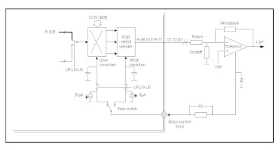
6. Three output video signal (RGB signal) is assumed as the current that flows to the CRT cathode. Drive level coming into the cathode tube is always diadjust by CCC loop (Continues Cathode Calibration) and feedback currents in pass to Black Current Input pin 50.

7. CCC loop works as a stabilizer against the black level and drive the cathode in a loop (continuous) to the RGB signal in order to obtain the proper offset and gain.

CCC Loop Application


    Total Pageviews