Showing posts with label for. Show all posts

Wednesday, 2 October 2013

0 Comments
Posted in Arrangement, Art, Business

USB Power Injector For External Hard Drives

header01

A portable USB hard drive is a great way to back up data but what if your USB ports are unable to supply enough "juice" to power the drive? A modified version of the Silicon Chip Usb Power Injector is the answer. For some time now, the author has used a portable USB hard drive to back up data at work. As with most such drives, it is powered directly from the USB port, so it doesn’t require an external plug pack supply.

Projects Picture:

finished-projects

In fact, the device is powered from two USB ports, since one port is incapable of supplying sufficient current. That’s done using a special USB cable that’s supplied with the drive. It has two connectors fitted to one end, forming what is basically a "Y" configuration (see photo). One connector is wired for both power and data while the other connector has just the power supply connections. In use, the two connectors are plugged into adjacent USB ports, so that power for the drive is simultaneously sourced from both ports.

USB Cable:

usb-cables

An external USB hard drive is usually powered by plugging two connectors at one end of a special USB cable into adjacent USB ports on the computer. This allows power to be sourced from both ports. According to the USB specification, USB ports are rated to supply up to 500mA at 5V DC, so two connected in parallel should be quite capable of powering a portable USB hard drive – at least in theory.

Complete Project:

Complate project-in-box

Unfortunately, in my case, it didn’t quite work out that way. Although the USB drive worked fine with several work computers, it was a "no-go" on my home machine. Instead, when it was plugged into the front-panel USB ports, the drive repeatedly emitted a distinctive chirping sound as it unsuccessfully tried to spin up. During this process, Windows XP did recognise that a device had been plugged in but that’s as far as it went – it couldn’t identify the device and certainly didn’t recognize the drive. Plugging the drive into the rear-panel ports gave exactly the same result. The problem wasn’t just confined to this particular drive either. A newly-acquired Maxtor OneTouch4 Mini drive also failed to power up correctly on my home computer, despite working perfectly on several work computers.

Circuit diagram:

circuit diagram

The revised USB Power Injector is essentially a switch and a 5V regulator. The Vbus supply from USB socket CON1 turns on transistor Q1 which then turns on power Mosfet Q2. This then feeds a 6V DC regulated supply from an external plug pack to regulator REG1 which in turn supplies 5V to USB socket CON2.

Source: Silicon Chip 26 June 2008

Thursday, 26 September 2013

0 Comments
Posted in Arrangement, Art, Business

SSB Add On For AM Receivers

Given favourable radio wave propagation, the shortwave and radio amateur band are chock-a-block with SSB (single-sideband) transmissions, which no matter what language they’re in, will fail to produce intelligible speech on an AM radio. SSB is transmitted without a carrier wave. To demodulate an SSB signal (i.e. turn it into intelligible speech) it is necessary to use a locally generated carrier at the receiver side. As most inexpensive SW/MW/LW portable radios (and quite a few more expensive general coverage receivers) still use plain old 455 kHz for the intermediate frequency (IF), adding SSB amounts to no more than allowing the radio’s IF to pick up a reasonably strong 455-kHz signal and let the existing AM demodulator do the work.


The system is called BFO for ‘beat frequency oscillator’. The heart of the circuit is a 455-kHz ceramic resonator or crystal, X1. The resonator is used in a CMOS oscillator circuit supplying an RF output level of 5 Vpp. which is radiated from a length of insulated hookup wire wrapped several times around the receiver. The degree of inductive coupling needed to obtain a good beat note will depend on the IF amplifier shielding and may be adjusted by varying the number of turns. All unused inputs of the 4069 IC must be grounded to prevent spurious oscillation.

Monday, 23 September 2013

0 Comments
Posted in Arrangement, Art, Business

AUTO RETRY fOR MAX1637 STEP DOWN CONTROLLER ELECTRONIC DIAGRAM


AUTO RETRY fOR MAX1637 STEP-DOWN CONTROLLER ELECTRONIC DIAGRAM

On microprocessor supervisor (IC1), an internal power-fail comparator and manual-reset circuitry (MR) is included. IC1s PFI input will detect when Vout(1.8V) is above the internal reference voltage (1.25V). Active-low RESET and active-low SHDN go high after a timeout delay of 140ms, re-enabling IC2. The other way to re-enabling IC2 is when the supply voltage is first switched on : the 3.5V rail stabilizes after 140ms will cause active-low RST to go high and activate IC2.The active-low PFO output produces a pulse using the internal 60k pull-up resistor and external 0.1 uF capacitor if Vout falls below 1.25V (due to a short circuit, for instance).

Thursday, 1 August 2013

0 Comments
Posted in Arrangement, Art, Business

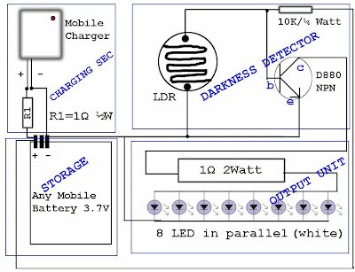
Reuse Old Mobile Phone Battery for LED lighting

Normally mobile batteries have a lifespan of 2-5 years under normal usage. But then we have to replace them. Nowadays there are cheap replacement batteries which cost no more than 1$. But these low cost batteries run only 6-12 months. What to do with the used batteries, which can’t be reused in mobiles? Well, easy solution is to use the batteries in a circuit that requires less current. We can use them for LED lighting.

Do you have old unusable Mobile battery?
Hacks and Mods: Reuse Old Mobile Phone Battery for LED lighting
Normally mobile batteries have a lifespan of 2-5 years under normal usage. But then we have to replace them. Nowadays there are cheap replacement batteries which cost no more than 1$. But these low cost batteries run only 6-12 months. What to do with the used batteries, which can’t be reused in mobiles?
Hacks and Mods: Reuse Old Mobile Phone Battery for LED lighting
Well, easy solution is to use the batteries in a circuit that requires less current. We can use them for LED lighting. Thus your automatic lighting emergency light is ready which runs by your waste Mobile Battery.

Sunday, 21 April 2013

0 Comments
Posted in Arrangement, Art, Business

Step Up Converter For 20 LEDs

The circuit described here is a step-up converter to drive 20 LEDs, designed to be used as a home-made ceiling night light for a child’s bedroom. This kind of night light generally consists of a chain of Christmas tree lights with 20 bulbs each consuming 1 W, for a total power of 20 W. Here, in the interests of saving power and extending operating life, we update the idea with this simple circuit using LEDs. 

Power can be obtained from an unregulated 12 V mains adaptor, as long as it can deliver at least about 330 mA.  The circuit uses a low-cost current-mode controller type UCC3800N, reconfigured into voltage mode to create a step-up converter with simple compensation. By changing the external components the circuit can easily be modified for other applications. To use a current-mode controller as a voltage-mode controller it is necessary to couple a sawtooth ramp (rising from 0 V to 0.9 V) to the CS (current sense) pin, since this pin is also an input to the internal PWM comparator.

Circuit diagram :
Step-up Converter For 20 LEDs -Circuit-Diagram
Step-up Converter For 20 LEDs Circuit Diagram

The required ramp is present on the RC pin of the IC and is reduced to the correct voltage range by the voltage divider formed by R3 and R2. The RC network formed by R4 and C6 is dimensioned to set the switching frequency at approximately 525 kHz. The comparator compares the ramp with the divided-down version of the output voltage produced by the potential divider formed by R6 and R7. Trimmer P1 allows the output voltage to be adjusted. This enables the current through the LEDs to be set to a suitable value for the devices used. The UCC3800N starts up with an input voltage of 7.2 V and switches off again if the input voltage falls below 6.9 V. The circuit is designed so that output voltages of between 20 V and 60 V can be set using P1.

This should be adequate for most cases, since the minimum and maximum specified forward voltages for white LEDs are generally between 3 V and 4.5 V. For the two parallel chains of ten LEDs in series shown here a voltage of between 30 V and 45 V will be required. The power components D1, T1 and L1 are considerably over specified here, since the circuit was originally designed for a different application that required higher power. To adjust the circuit, the potentiometer should first be set to maximum resistance and a multimeter set to a 200 mA DC current range should be inserted in series with the output to the LEDs. Power can now be applied and P1 gradually turned until a constant current of 40mA flows. The step-up converter is now adjusted correctly and ready for use.


www.ecircuitslab.com

Friday, 12 April 2013

0 Comments
Posted in Arrangement, Art, Business

Preamplifier for RF Sweep Generator

The RF sweep frequency generator (‘wobbu-lator’) published in the October 2008 difficulty of Elektor has a receiver option that enables the instrument for use as an instantaneous conversion receiver. This receiver does alternatively have a noise floor of best –80 dBm, which in reality will need to have been –-107 dBm to obtain a sensitivity of 1 µV. So, for a just proper receiver sommore acquire is required. A wideband amplifie however, generates a number of additional noisas well and as a consequence is not going to resuin a lot of an growth.  As an test, the author developed a make a selectionive receiver with a bandwidth of about four MHz. Because a achieve of as a minimum 35 dB is required, the preamplifier consists of two amplifying elements. 

The enter amplifier is designed round a dual gate MOSFET, sort BF982. This element produces moderately little noise but pro-vides various achieve. The output stage makes use of a BFR91A for some further achieve. Preamplifiers where both the gate and the drain are tuned steadily fight with comments by means of their  inside capacitance. Here, the drain circuit has a rather low impedance, which prevents this from taking place. In the prototype that used to be tested, the input and output are located at proper perspectives with appreciate to one another to stop inductive coupling (see photo). Despite the high achieve, the amplifier used to be completely steady even with none defensive.  The two air-cored coils in the circuit each encompass four flips and have an interior  diameter  of  6 mm,  constructed from 1-mm diameter silvered copper wire and with a tap after 1 flip.

Circuit diagram :
Preamplifier for RF Sweep Generator Circuit Diagram
 
The amplifier is principally intended for the one hundred forty four MHz beginner band, however with different coils can also be used for the FM broadcast band, as an instance. FM detection is finished via tuning near the brink of the IF filter. At an offset of 15 kHz this is only a few dB lower than on the centre of the pass-band, so that damping just isn't no longericeable. The measured sensitivity within the 2 m band used to be about 1 µV (6 dB).A good antenna always make a contributions to the reception, after all. A wideband (scanner) outside antenna will provide excellent end results. Adding this wobbulator/receiver possibility ends up in a nice reveal receiver. By environment the scan frequencies of the spectrum analyser to a hundred and forty four and 146 MHz (or 148 MHz the place applicable), any signal within this vary is in an instant visible. When a signal is detected it's basically a case of clicking the scan stop button and then clicking on the sign within the display window the usage of the right mouse howeverton. 

After this, the receiver switches instantly to this frequency and that you presumably can be ready to take heed to the signal. You can due to this fact resume the scanning so that that you could be ready to proceed to look for different alerts. For narrowband FM detection you want to make a choice the FMN howeverton in the window for the receiver and this then gives the required offset for the threshold detection at 25 kHz bandwidth. This value is adjustable by the use of the ‘setting’ menu (default is 12,500 Hz) and might be modified experimentally for best possible end results. To energy the circuit you will must use a 9-V battery. It can additionally be possible to power the amplifier immediately from the RF sweep generator, if output capacitor C6 is changed with a link; in the ‘options’ menu you're going to then must make a choice the choice ‘use probe’.

 http://www.ecircuitslab.com/2011/12/preamplifier-for-rf-sweep-generator.html

Thursday, 11 April 2013

0 Comments
Posted in Arrangement, Art, Business

Lambda Probe Readout For Carburettor Tuning

A lambda probe (or oxygen sensor) can be found on the exhaust system of most cars running on unleaded fuel. Having reached its normal operating temperature (of about 600 degrees Celsius!) the lambda probe supplies an output voltage proportional to the amount of residual oxygen measured in the exhaust gas.

This information is indicative of, among others, the air/fuel ratio supplied by the carburetor(s) and hence the combustion efficiency. In modern car (and motorcycle) engines, this information is used to (electronically) adjust engine parameters like ignition timing and fuel injection. The indicator described here is intended for permanent installation on a motorcycle of which the air/fuel ratio needed to be watched, with the obvious aim engine power tuning after fitting a different set of carburetors. Apart from this obvious technical use the unit’s bright LEDs will no doubt attract the attention of curious motorcyclists.

Lambda Probe Readout For Carburettor Tuning

At the local junkyard a single-wire lambda probe may be salvaged from a wrecked car. Once a suitable nut has been found, the probe can screwed into the exhaust pipe of the motorcycle, at about 30 cm from the cylinders.  Since we’re talking of welding and drilling in an expensive (chrome-plated) exhaust pipe, you may find that actually fitting the probe is best left to specialists!  The starting point for the design of a suitable electronic indicator is that in the noble art of carburetor tuning an air/fuel ratio of 14.7 to 1 is generally considered ‘perfect’, the range covering 16.2 to 1 (‘lean’) to 11.7 to 1 (‘rich’). The perfect ratio typically corresponds to a probe output voltage of 0.45 V. 

 Referring to the circuit diagram, that is the input level at which 5 of the 10 LEDs will light, including the green one, D5. If one of the red LEDs lights, the mixture is definitely too rich. Note that in general it is better to have a mixture that is a little to rich than one that’s on the lean side, hence a yellow LED lights between the green LED and the first red one. Also note that the engine needs to be at its normal operating temperature before a meaningful indication is obtained.


streamcircuits

Wednesday, 10 April 2013

0 Comments
Posted in Arrangement, Art, Business

Test Beeper For Your Stereo

The test beeper generates a sinusoidal signal with a frequency of 1,000 Hz, a common test  frequency for audio amplifiers.  It consists of a classical Wien- Bridge oscillator (also known as  a Wien-Robinson oscillator). The network that determines the  frequency consists here of a series connection of a resistor and  capacitor (R1/C1) and a parallel connection (R2/C2), where  the values of the resistors and  capacitors  are  equal  to  each  other. This network behaves, at  the oscillator frequency (1 kHz  in this case), as two pure resistors. The opamp (IC1) ensures  that the attenuation of the net- work  (3  times)  is  compensated  for.  In  principle  a  gain  of  3 times should have been sufficient to sustain the oscillation,  but  that  is  in  theory.  Because  of tolerances in the values, the  amplification needs to be (automatically) adjusted.

Circuit diagram:
Test Beeper For Your Stereo circuit-Diagram
Test Beeper For Your Stereo circuit Diagram

Instead of an intelligent amplitude  controller  we  chose  for  a  somewhat simpler solution. With  P1, R3 and R4 you can adjust  the gain to the point that oscillation takes place. The range of P1 (±10%) is large enough the cover the tolerance range. To sustain  the oscillation, a gain of slightly  more than 3 times is required,  which  would,  however,  cause  the amplifier to clip (the ‘round-trip’ signal becomes increasingly  larger, after all). To prevent this  from happening, a resistor in se-ries with two anti-parallel diodes  (D1 and D2) are connected in  parallel  with  the  feedback  (P1  and R3). If the voltage increases to the point that the threshold  voltage of the diodes is exceed-ed, then these will slowly start to  conduct.

The consequence of this  is that the total resistance of the  feedback  is  reduced  and  with  that  also  the  amplitude  of  the  signal. So D1 and D2 provide a  stabilising function. The distortion of this simple oscillator, after adjustment of P1 and  an output voltage of 100 mV (P2  to  maximum)  is  around  0,1%.  You can adjust the amplitude of  the output signal with P2 as required for the application. The  circuit is powered from a 9-V battery. Because of the low current  consumption  of  only  2 mA  the  circuit will provide many hours  of service.
Author :Ton Giesberts  - Copyright : Elektor Electronics
0 Comments
Posted in Arrangement, Art, Business

Circuit modifications for operating 150 LEDs


Parts List

R1 = 220 Ohms, 1/2 watt
R2 = 100Ohms, 2 watts,
RL = All 22 Ohms, 1/4 watt,
C1 = 100uF/25V,
D1,2,3,4,6,7,8 = 1N5408,
D5 = 1N4007
T1 = AD149 or similar,
Transformer = 0-6V, 500mA

Sunday, 7 April 2013

0 Comments
Posted in Arrangement, Art, Business

Trans Impedance Amplifier for DAC Outputs Using LH4117 Single IC Chip


This is a circuit for trans-impedance amplifier that using to DAC output. This circuit is based on LF4117 that is an excellent match to amplify the output of DACs like the DAC0800. The fast settling time of 9 ns to 0.02% does not degrade the performance of the DAC. On the other hand, the DAC0800 provides complimentary current outputs, which are current sinks and do not need a fixed voltage to work accurately. This is the figure of the circuit.

The DAC0800 is fed a reference current of IREF e 2 mA into pin 14. This is achieved by the LH0070 voltage reference with 10V output. A resistance of 5 kX (R1 a R2) is connected to pin 14, which is a virtual ground, thus providing the reference current of 2 mA. The grounded pin 15 provides the reference voltage for pin 14. The DAC has eight current sinks, each set for half the current of the previous one. Through switches, controlled by the input logic levels, their open collectors are connected to one of the two outputs. The sum of the output currents I1 and I2 equals the reference current of 2 mA. Because of the open collector configuration the outputs do not have to be tied to a fixed voltage level. The outputs of the DAC0800 are connected to the inputs of the LH4117 through 100X resistors (R4 and R5). This is to decouple the inputs of the amplifier from the output capacitance of the DAC, which is typically 23 pF to 30 pF. Especially the inverting input is sensitive to capacitance. [Schematic’s circuit source: National Semiconductor Notes].

Saturday, 6 April 2013

0 Comments
Posted in Arrangement, Art, Business

Best Start up Aid for PCs

Since one of the servers owned by the author would not start up by itself after a power failure this little circuit was designed to perform that task. 

The older PC that concerned did have a standby state, but no matching BIOS set-ting that allows it to start up unattended. Although a +5 V standby supply voltage is available, you always have to push a but-ton for a short time to start the computer up again. Modern PCs often do have the option in the BIOS which makes an automatic start after a power outage possible. After building in the accompanying circuit, the PC starts after about a second. Incidentally, the push-button still functions as before.
 Start-up-Aid for-PCs-Circuit Diagram

The circuit is built around two golden oldies: a NE555 as single-shot pulse generator and a TL7705 reset generator. The reset generator will generate a pulse of about 1 second after the supply voltage appears. The RC circuit between the TL7705 and the NE555 provides a small trigger pulse during the falling edge of the 1 second pulse. The NE555 reacts to this by generating a nice pulse of 1.1RC. During that time the output transistor bridges the above mentioned pushbutton switch of the PC, so it will start obediently. 

Pcs
Other applications that require a short duration contact after the power supply returns are of course also possible.


Author : Egbert Jan van den Bussche – Copyright : Elektor

    Total Pageviews