Friday, 27 December 2013

0 Comments
Posted in Arrangement, Art, Business

PC Heat Monitor

The PC processor generates very high temperature during its operation which is dissipated by the large heat sink placed above the processor. If the heat sink assembly is not tight with the processor or the cooling fan is not working, PC enters into the Thermal shutdown mode and will not boot up. If the PC is not entering into thermal shutdown, the high temperature can destroy the processor. This simple circuit can be placed inside the PC to monitor the temperature near the processor. It gives warning beeps when the temperature near the heat sink increases abnormally. This helps to shutdown the PC immediately before it enters into Thermal shutdown.

Circuit Project: PC Heat Monitor Circuit 

The circuit uses a Piezo element (one used in Buzzer) as the heat sensor. The piezo crystals reorient when subjected to heat or mechanical stress and generates about one volt through the Direct piezoelectric property. IC1 is designed as a voltage sensor with both the inputs tied through the capacitor C1.The non inverting input is connected to the ground through R1 to keep the output low in the standby state. The inputs of IC1 are very sensitive and even a minute change in voltage level will change the output state.

Circuit Project: PC Heat Monitor Circuit

In the standby mode, both the inputs of IC1 are balanced so that output remains low. When the Piezo element accepts heat, it generates a minute voltage which will upset the input balance and output swings high. This triggers LED and Buzzer. Capacitor C2 gives a short lag before the buzzer beeps to avoid false triggering. Warning beep continues till the piezo element cools.

Note: Enclose the circuit inside the PC with the piezo element close to the heat sink of the processor. Adjust the distance between the piezo element and heat sink so as to keep the circuit standby in the normal condition. The piezo element can sense a 10 degree rise in temperature from a distance of 5 cms. Power to the circuit can be tapped from the 12 volt line of SMPS.

Thursday, 26 December 2013

0 Comments
Posted in Arrangement, Art, Business

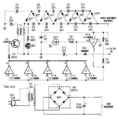
High Voltage DC Generator Circuit Diagram

This circuit is fed from a 12-V de power supply. The input to the circuit is then amplified to provide a 10,000-Vdc output. The output of the up-converter is then fed into a 10 stage, high-voltage multiplier to produce an output of 10,000 Vdc.


High Voltage DC Generator Circuit Diagram

High Voltage DC Generator Circuit Diagram

Wednesday, 25 December 2013

0 Comments
Posted in Arrangement, Art, Business

7805 Voltage Regulator Circuit

A voltage regulator is used to produce a constant linear output voltage. It’s generally used with AC to DC power supply. And also it can be used as well as a DC to DC voltage converter . To regulating low voltage, most used device is one single IC. 7805, 7812, 7905 etc. 78xx series are design for positive and 79xx series are for Negative voltage regulator.

7805 is a three terminal +5v voltage regulator IC from 78XX chips family. See 7805 pinout below. LM78XX series are from National Semiconductor. They are linear positive voltage regulator IC; used to produce a fixed linear stable output voltage.  National Semiconductor has also negative voltage regulator chips family, they indicate with LM 79XX. 78xx is used more than 79xx because negative voltage has a few usability purposes as we see.
I was previously posted a 5v regulated power supply circuit using 7805 IC, that circuit and this 7805 voltage regulator circuit is almost the same.


Circuit diagram of 7805 Voltage Regulator


Fig: 7805 Voltage Regulator Circuit


7805 pinout


7805 pinout, pin diagram
Fig: Pinout of 7805

Its output voltage is +5V DC that we need. You can supply any voltage in input; the output voltage will be always regulated +5V. But my recommendation is, don’t supply more than 18V or less than 8V in input. There used two capacitors in this voltage regulator circuit, they aren’t mandatory to use. But it will be best if you use them. They helped to produce a smooth regulated voltage at output. Use electrolyte capacitor instead of ceramic capacitor.

One limitation of 7805 I have found that is its output current 1A maximum. Otherwise it is a good voltage regulator if you are happy with 1A. But if   you need over 400mA current in output then you should use a Heat Sink with IC LM7805. Otherwise it may fall damage for overheating.

Tuesday, 24 December 2013

0 Comments
Posted in Arrangement, Art, Business

Pre regulated High Voltage Power Supply Circuit Diagram

This Pre-regulated High Voltage Power Supply Circuit Diagram triacs selects the tap on main transformer Tl, which provides the proper, pre-regulated voltage to the secondary regulator. T2 and its associated components comprise the secondary regulator. The ADC 0804, IC1, digitizes a voltage-feedback signal from the secondary regulator`s output. 

 Pre-regulated High Voltage Power Supply Circuit Diagram

Pre-regulated High Voltage Power Supply Circuit Diagram


The MC1415 De-multiplexer, IC2, decodes the digitizer`s output. IC2, in turn, drives Tl`s opto-isolated triacs via the 74LS240 driver chip, IC3, and associated opto-isolators. Transformer T3 samples the circuit`s current output. The auxiliary, 12 V winding on Tl ensures noload starting. The combination of op amp IC5 and the inverting transistor, Ql, square this current signal. 

The output of Ql is the CLK signal, which triggers one-half of the one shot, IC4A, to begin the circuit`s AID conversion. The one shots` periods are set to time out within 1l2 cycle of the ac input. Upon completion of its AID conversion, ICl`s INTR output triggers the other half of the one shot, IC4B, which enables the converter`s data outputs. The rising edge of the CLK signal resets the one shot and latches the new conversion value into IC2. The latch, associated driver, and optoisolator trigger a selected triac according to the latest value of the voltage-feedback signal, V, . Keep enjoying dont forget click on share button .


Monday, 23 December 2013

0 Comments
Posted in Arrangement, Art, Business

Mobile Car Stereo Player

Using a mobile phone while driving is dangerous. It is also against the law. However, you can use your mobile phone as a powerful music player with the help of a stereo power amplifier. This does away with the need of a sophisticated in-dash car music system. Most mobile phones have a music player that offers a number of features including preset/manual sound equalisers. They have standard 3.5mm stereo sockets that allow music to be played through standard stereo headphones/sound amplifiers. Nokia 2700 classic is an example.

Mobile Car Stereo Player Circuit Diagram

Circuit of mobile car stereo player

A car audio amplifier with 3.5mm socket can be designed and simply connected to the mobile phone output via a shielded cable with suitable connectors/jacks (readymade 3.5mm male-to-male connector cable is a good alternative). Fig. 1 shows the circuit of car stereo player. It is built around popular single-chip audio power amplifier TDA1554Q (IC1). The TDA1554Q is an integrated class-B power amplifier in a 17-lead single-in-line (SIL) plastic power package.

IC TDA1554Q contains four 11W identical amplifiers with differential input stages (two inverting and two non-inverting) and can be used for single-ended or bridge applications. The gain of each amplifier is fixed at 20 dB. Here it is configured as two 22W stereo bridge amplifiers. The amplifier is powered from the 12V car battery through RCA socket J2. Diode D1 protects against wrong-polarity connection. LED1 indicates the power status.

Stereo Jack :
3.5mm stereo socket and (b) 3.5mm

(a) 3.5mm stereo socket and (b) 3.5mm Stereo Jack

Connect stereo sound signal from the 3.5mm headset socket of the mobile phone to audio input socket J1. When you play the music from your mobile, IC1 amplifies the input. The output of IC1 is fed to speakers LS1 and LS2 fitted at a suitable place in your car. Electrolytic capacitor C5 connected between pin 4 of IC1 and GND improves the supply-voltage ripple rejection. Components R2 and C4 connected at mute/standby pin (pin 14) of IC1 eliminate the switch on/off plop. The circuit is quite compact. A good-quality heat-sink assembly is crucial for IC1. Fig. 2 shows the stereo socket and stereo jack.

Proposed enclosure
Proposed enclosure

Assemble the circuit on a general-purpose PCB and enclose in a suitable cabinet. Small dimensions of the power amplifier make it suitable for being enclosed in a plastic (ABS) case with vent holes. Signal input socket, speaker output terminals, on/off switch, indicator, fuse holder and power supply socket are best located on the front panel of the enclosure as shown in Fig. 3.

Source : http://www.ecircuitslab.com/2012/04/mobile-car-stereo-player.html

Sunday, 22 December 2013

0 Comments
Posted in Arrangement, Art, Business

best cell phone jammer will stop working immediately

The over heat of best cell phone jammer should be timely dissipated.
Chinas mobile advertising does not scale, but it must embark on the road and internet advertising, but more business model remains to be explored. Several models of mobile media advertising. In China, mobile media advertising model can be divided into the following categories: the earliest provider of wireless advertising professional Focus wireless, using this model. There are two specific advertising: Point report, and direct report. Point report, through the identification of the users identity with the aid of technical means to fully tap the user attributes, automatically match the user properties to cater to user preferences ads to the users see on the page, different people see different ads precise The sentinel marketing. And get these best cell phone jammer directly from the supplier in the a shorter time.
Difficult to sell to a pack of cigarettes a woman, though she had the purchasing power, but she did not need, when you pass her cigarette advertising, is still spam. In other words, no will to produce spam, that is the wrong content delivery to the wrong object, although the advertising arrival rate, but not the demand, the result is still negative. SMS group sending, are examples. Win-win is the last word. The future of mobile advertising is first and foremost to be able to obtain permission from the customer, in other words, the ad itself is a value-added behavior for the audience, you can achieve a win-win of the advertisers and the audience will never users interfere. The inspection of some other wireless signals can be carried out by best cell phone jammer .
Type of mobile advertising is popular. Through a series of positioning and data analysis, cell text messaging information targeted to send to give advertising related to the user, for example, passengers waiting at the airport will often receive a discount ticket information. Business services, exhibition, hotel, shopping malls, automobile, FMCG, banking, real estate and other industries are beginning to Cell SMS platform to launch mobile advertising. "Mobile advertising mobile marketing is the next step." Communication University of China Vice-Chancellor Ding Junjie, "However, the main problems facing the mobile advertising is still lack a lot of professional standards, such as results-based monitoring of mobile advertising standards, the standard of the quotation system, advertising reach the standard of the cost of thousands of users and so on. And at the same time best cell phone jammer will stop working immediately.
Internet users are mainly concentrated in the eastern coastal areas and some inland provinces.

Saturday, 21 December 2013

0 Comments
Posted in Arrangement, Art, Business

Build a 12 14 Volt 3A Anti RF Filtered Power supply Circuit Diagram

How to Build a 12-14 Volt 3A - Anti-RF Filtered Power supply Circuit Diagram. This is not easy but you can do it . This Anti-RF Filtered Power supply Circuit Diagram is dedicated for use with rf equipments like, linear amplifiers, transmitters, receivers, and in every application that clean an-noisy signal is required. 

The circuit is very simple and you can drive it with a 220V/18V/3A transformer at the pins 1and 2.The regulator used here is the LM350K and make sure you place a good heat-sink to it because it gets too hot if current gets near to 3A. 

 12-14 Volt 3A - Anti-RF Filtered Power supply Circuit Diagram

12-14 Volt 3A - Anti-RF Filtered Power supply Circuit Diagram


Parts list
R1 = 220 Ohm 1/4W
R2 = 1,8 KOhm 1/4W
R3 = 330 Ohm 1/4W
 P1 = 100 Ohm
C1,C2,C3 = 4.700uf/25V
C4 = 100pf ceramic
C6 = 100uf/25V electrolitic
D1..4 = 1N5400-4 or RAX GI 837U
F1 = 5A
IC1 = LM350K

For Data Sheet Contact with us here

Friday, 20 December 2013

0 Comments
Posted in Arrangement, Art, Business

Loudspeaker Thump Remover Eliminator

Some solid state power amplifiers make a loud thump when turned on or off. The thump you hear when you turn on or turn off your amplifier is caused by the sudden application or interruption in supply voltages to the amplifier output stages. To remove the thump, the output signal must be delayed (and thus the transient) until the output voltage will reach a safe level for the speakers.

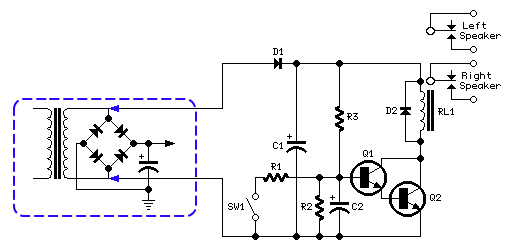
In the circuit diagram, resistor R3 and capacitor C2 form an RC network timer. When voltage is applied to the circuit, R3 allows C2 to charge to about 1.2V. The transistors Q1 and Q2 are connected in a Darlington configuration and are then non-conducting until the charge across C2 does not exceed the sum of the base-emitter voltage of Q1 and Q2, i.e. 0.6V for each transistor for a total of 1.2V.

Loudspeaker Thump Remover Circuit Diagram

Once the voltage across C2 exceeds 1.2V, Q1 and Q2 immediately run into saturation, activating the relay RL1, which completes the circuit between the amplifier and speaker systems. The power supply circuit consists of a simple rectifier diode and a low value filter capacitor (D1 and C1). The ac voltage required is taken from the secondary winding of the transformer available in your amplifier.

In many cases, when dual supply is present and therefore the secondary winding is center tapped, the circuit can be connected across the central tap and one of the two outer leads of the winding or, on the contrary, across the whole winding. In the latter case, the available voltage will be twice the first case. This choice will affect also the coil operating voltage of the relay used.

You can choose a relay having a coil rated at 12V dc for a secondary winding ac voltage up to 15V; a 24V relay for an ac voltage up to 30V (or two SPST 12V relays wired in series, one for each channel). For higher ac voltages use a 48V relay or two SPST 24V relays wired in series. SW1 and R1 provide an optional mute facility: closing SW1 the Relay will go off and therefore the amplifier will be muted.

Notes:


  • After turn on, the relay will be activated with a delay of about 3 - 5 seconds. The delay time can vary by changing the values of R3 and/or C2.
  • If you do not want the mute function, SW1 and R1 can be omitted.
  • If two relays wired in series are employed, the added relay must have its own clamping diode connected across the coil.
  • When a voltage supply of about 48V is used, substitute BC337 transistors with BC546 types.


Thursday, 19 December 2013

0 Comments
Posted in Arrangement, Art, Business

THIEF ALARM WITHOUT IC NE555


THIEF ALARM (WITHOUT IC NE555)
INDRODUCTION:-
This is the easiest way to make a thief alarm. If you know how to make an ordinary electric circuit, this circuit would be very simple than the other method.
MATERIALS REQUIRED:-
11)      Breadboard                                               1
22)      12v/230v Transformer                                1(2)
33)      Buzzer                                                        1
44)      LED                                                           4
55)      LDR(RESISTANCE IN DARKNESS       1
66)      Resistor 48 K Ohms                                   2
77)      Resistor 100 ohms                                      2
PROCEDURE:-  
Take the breadboard and connect the 12v/230v transformer to the pin numbers 5 and 10.connect the 100 ohms resistors to the pins 1b and 5b.Then connect one wire of the transformer directly to the resistors 48 k ohms leading to the +ve terminals of the buzzer and the LED. Then connect the next wire of the transformer to the LDR’s first terminal then connect the next terminal of the LDR to the –ve terminals of the buzzer and LED. Now switch off the light.When the intruder switches on his torch the
                                Circuit
    

Wednesday, 18 December 2013

0 Comments
Posted in Arrangement, Art, Business

Simple 12 V Battery Charger Circuit Diagram

This 12 V Battery Charger Circuit Diagram is a high performance charger for gelled electrolyte lead-acid batteries. Charger quickly recharges battery and shuts off at full charge. Initially, charging current is limited to 2A. As the battery voltage rises, current to the battery decreases, and when the current has decreased to 150 mA, the charger switches to a lower float voltage preventing overcharge.

 12 V Battery Charger Circuit Diagram

12 V Battery Charger Circuit Diagram


When the start switch is pushed, the output of the charger goes to 14 V. As the battery approaches full charge, the charging current decreases and the output voltage is reduced from 14 V to about 12 5 V terminating the charging. Transistor Ql then lights the LED as a visual indication of full charge.

Tuesday, 17 December 2013

0 Comments
Posted in Arrangement, Art, Business

Circuit Diagram of Photocell Power Supply MAX630

This Circuit Diagram of Photocell Power Supply (MAX630) delivers either 4.8 or 7.2 V regulated at 15 mA with a 3-V input from a bank of photocells. R1 should be 453 k? for a 7.2-V output and 274 k? for a 4.8-Vdc output. Regulator efficiency is around 70%. This should be considered when selecting suitable solar cells.

Circuit Diagram of Photocell Power Supply (MAX630)

Circuit Diagram of Photocell Power Supply (MAX630)

Thursday, 10 October 2013

0 Comments
Posted in Arrangement, Art, Business

Portable Microphone Preamplifier

High headroom input circuitry, 9V Battery operation

This circuit is mainly intended to provide common home stereo amplifiers with a microphone input. The battery supply is a good compromise: in this manner the input circuit is free from mains low frequency hum pick-up and connection to the amplifier is more simple, due to the absence of mains cable and power supply. Using a stereo microphone the circuit must be doubled. In this case, two separate level controls are better than a dual-ganged stereo potentiometer. Low current drawing (about 2mA) ensures a long battery life.

Circuit Operation:

The circuit is based on a low noise, high gain two stage PNP and NPN transistor amplifier, using DC negative feedback through R6 to stabilize the working conditions quite precisely. Output level is attenuated by P1 but, at the same time, the stage gain is lowered due to the increased value of R5. This unusual connection of P1, helps in obtaining a high headroom input, allowing to cope with a wide range of input sources (0.2 to 200mV RMS for 1V RMS output).

Circuit diagram:

Portable Microphone Preamplifier Circuit Diagram

Portable Microphone Preamplifier Circuit Diagram

Parts:

P1 = 2.2K
R1 = 100K
R2 = 100K
R3 = 100K
R4 = 8.2K
R5 = 68R
R6 = 6.8K
R7 = 1K
R8 = 1K
R9 = 150R
C1 = 1uF-63V
C2 = 100uF-25V
C3 = 100uF-25V
C4 = 100uF-25V
C5 = 22uF-25V
Q1 = BC560
Q2 = BC550

Notes:

  • Harmonic distortion is about 0.1% @ 1V RMS output (all frequencies).
  • Maximum input voltage (level control cursor set at maximum) = 25mV RMS
  • Maximum input voltage (level control cursor set at center position) = 200mV RMS
  • Enclosing the circuit in a metal case is highly recommended.
  • Simply connect the output of this device to the Aux input of your amplifier through screened cable and suitable connectors.

Source : www.redcircuits.com

Wednesday, 9 October 2013

0 Comments
Posted in Arrangement, Art, Business

Fuse Monitor

The idea for this project may have come to me in a flash of inspiration, and its a very simple way to check if a fuse has blown without removing it from its holder. The simplicity of this circuit uses just two components, but with just one resistor and an LED this circuit gives visual indication of when a fuse has blown. LED1 is normally off, being "short circuited " by the fuse, F1. Should the inevitable "big-bang" happen in your workshop then LED1 will illuminate and led you know all about it! Please note that the LED will only illuminate under fault conditions, i.e. with a short circuit or shunt on the load. In this case the current is reduced to a safe level by R1.

Fuse Monitor Circuit Diagram

Tuesday, 8 October 2013

0 Comments
Posted in Arrangement, Art, Business

Cheap And Cheerful Transistor Tester

By using a simple visual indicating system, this small transistor tester allows you to run a quick ‘go/non-go’ check on NPN as well as PNP transistors. If the device under test is a working NPN then the green LED (D1) will flash, while the red counterpart will flash for a functional PNP device. However if the transistor is shorted, both LEDs will flash, and an open-circuit device will cause the LEDs to remain off. The circuit is based on just one CD4011B quad NAND gate IC, four passive parts and two LEDs. The fourth gate in the IC is not used and its inputs should be grounded.

Alternatively, you may want to connect its inputs and output in parallel with IC1.C to increase its drive power to the transistor test circuit. IC1.A and IC1.B together with R2, R3 and C1 form an oscillator circuit that generates a low-frequency square wave at pin 4. This signal is applied to the emitter of the transistor under test as well as to inverter IC1.C. The inverted signal from IC1.C and the oscillator output then drive the test circuit (LEDs, device under test, R1) in such a away that the voltage across that part of the circuit is effectively reversed all the time.

Cheap And Cheerful Transistor TesterFor example, with an NPN transistor under test, when pin 10 is High and pin 4, Low, current flows through LED D1 and the forward biased transistor. However, no current will flow when pins 10 and 4 change states, since the transistor is then reverse-biased. The green LED, D1, will therefore flash at the rate determined by the oscillator. As you would expect to happen, a PNP transistor will be forward biased when pin 10 is Low and 4, High, enabling current to flow through the red LED in that case.

A supply rail of around 3 V (two series connected 1.5-V batteries) should be adequate. To prevent damage to the transistor under test, supply voltages higher than 4.5 V should not be used. Because the LED currents are effectively limited to a few mA by the output of IC1.C (also slightly dependent on the supply voltage), it is recommended to use high-efficiency devices for D1 and D2.

Monday, 7 October 2013

0 Comments
Posted in Arrangement, Art, Business

Sound Effects Generator 2

This circuit uses the Holtek HT2884 IC to produce 8 different sound effects. All sound effects are generated internally by the HT2884 IC. Power is a 3 Volt battery, but the IC will work with any voltage between 2.5 and 5 Volts. Switch S1 is the on / off switch.
Sound Effects Generator 2 Circuit Diagram:
Sound Effects-Generator-2-Circuit Diagram
The output at pin 10 is amplified and drives a small 8 ohm loudspeaker. Pressing S3 once will generate all the sounds, one after another. S2 can be used to produce a single sound effect, next depression gives the next sound effect. There are 2 lazer guns, 1 dual tone horn sound, 2 bomb sounds, 2 machine gun sounds and a rifle shot sound. Standby current is about 1 uA at 3 Volt, so battery life is very economical.

The IC may be obtained from Maplin Electronics order code AZ52G

Sunday, 6 October 2013

0 Comments
Posted in Arrangement, Art, Business

LONG RANGE FM TRANSMITTER ELECTRONIC DIAGRAM


LONG RANGE FM TRANSMITTER ELECTRONIC DIAGRAM

This circuit works optimally by adding RF amplifier and antenna. Here is the schematic diagram :

Parts list :


  •     Diode D1 : BB109
  •     Resistor R1 : 10k ohm
  •     Resistor R2 : 100k ohm
  •     Resistor R3 : 180k ohm
  •     Resistor R4 : 4K7
  •     Resistor R5 : 15k ohm
  •     Resistor R6 : 68 ohm
  •     Resistor R7 : 470 ohm
  •     Resistor R8 : 39k ohm
  •     Resistor R9 : 10 ohm
  •     VR1 : 47k ohm
  •     VR2 : 22 ohm
  •     Capacitor C1-C3, C8 : 0.1 uF
  •     Capacitor C4 : 4.7 pF
  •     Capacitor C6 : 0.01 uF
  •     Capacitor C7 : 5.6 nF
  •     Capacitor C9 : 100 pF
  •     Transistor T1: BF494
  •     Transistor T2:2N3866
  •     Trimmer VC1-VC2 : 50p
  •     L1 : 4 round 20 cables SWG in plastic with 8mm diameter
  •     L2 : 2 round 24 cables SWG
  •     L3 : 7 round 24 cables SWG in plactic with 4mm diameter
  •     L4 : 7 round 24 cables SWG in ferrid bead


Saturday, 5 October 2013

0 Comments
Posted in Arrangement, Art, Business

Frequency Doubler

If you are working at frequencies of the order of 850MHz to 4GHz and find that a frequency multiplier is required, the HMC 187, HMC 188 and HMC 189 (see table) frequency doubler may be just the solution you are looking for. The isolation performance of these devices ensures that the input frequency (fin) and its harmonics 3fin and 4fin are attenuated by 35dB relative to the wanted output frequency 2fin. This excellent isolation specification reduces the need for additional output filtering and is also an advantage where several doublers are connected in series to produce four or eight times the input frequency.

Frequency Doubler Circuit DiagramThe tiny outline of the HMC18x- series device occupies a board area of 3mm by 4.8mm and measures just 1.07 mm high. Internally the device contains balanced to unbalanced transformers (baluns) to match the doubler circuit with the output and input. The doubler circuit itself is passive and comprises a full wave Schottky diode bridge rectifier. The monolithic baluns which are integrated on-chip give the device a relatively high low-frequency roll-off at 850MHz.

Table of Frequency Doubler Circuit DiagramLower frequencies can also be multiplied but the conversion loss factor (given as typically 15 dB) will increase. The input and output are matched for 50 Ohm operation and the input signal level should be of the order of +15dBm which will give a output level of approximately 0dBm. The main characteristics of the three versions of this device are summarized in the table above.

Friday, 4 October 2013

0 Comments
Posted in Arrangement, Art, Business

Mains Slave Switcher Circuit

There are many situations where two or more pieces of equipment are used together and to avoid having to switch each item on separately or risk the possibility of leaving one of them on when switching the rest off, a slave switch is often used. Applications which spring to mind are a computer/printer/scanner etc or audio amplifier/record deck/tuner combinations or perhaps closest to every electronics enthusiast’s heart, the work bench where a bench power supply/oscilloscope/soldering iron etc are often required simultaneously. The last is perhaps a particularly good example as the soldering iron, often having no power indicator, is invariably left on after all the other items have been switched off. Obviously the simplest solution is to plug all of the items into one extension socket and switch this on and off at the mains socket but this is not always very convenient as the switch may be difficult to reach often being behind or under the work bench. Slave switches normally sense the current drawn from the mains supply when the master unit is switched on by detecting the resulting voltage across a series resistor and switching on a relay to power the slave unit(s).
mains-slave-switcher-circuit-diagramq
This means that the Live or Neutral feed must be broken to allow the resistor to be inserted. This circuit, which is intended for switching power to a work bench when the bench light is switched on, avoids resistors or any modifications to the lamp or slave appliances by sensing the electric field around the lamp cable when this is switched on. The lamp then also functions as a ‘power on’ indicator (albeit a very large one that cannot be ignored) that shows when all of the equipment on the bench is switched on. The field, which appears around the lamp cable when the mains is connected, can be sensed by a short piece of insulated wire simply wrapped around it and this is amplified by the three stage amplifier which can be regarded as a single super-transistor with a very high gain. The extremely small a.c. base current results in an appreciable collector current which after smoothing (by C3) is used to switch on a relay to power the other sockets. Power for the relay is obtained from a capacitor ‘mains dropper’ that generates no heat and provides a d.c. supply of around 15 volts when the relay is off.
Circuit diagram:
mains-slave-switcher-circuit-diagramw 
The output current of this supply is limited so that the voltage drops substantially when the relay pulls in but since relays require more current to operate them than they do to remain energized, this is not a problem. Since the transistor emitter is referenced to mains Neutral, it is the field around the mains Live which will be detected. Consequently, for correct operation the Live wire to the lamp must be switched and this will no doubt be the case in all lamps where the switch is factory fitted. In case of uncertainty, a double-pole switch to interrupt both the Live and Neutral should be used. The sensitivity of the circuit can be increased or decreased as required by altering the value of the T2 emitter resistor. The sensing wire must of course be wrapped around a section of the lamp lead after the switch otherwise the relay will remain energized even when the lamp has been switched off. The drawing shows the general idea with the circuit built into the extension socket although, depending on the space available an auxiliary plastic box may need to be used.
Warning:
The circuit itself is not isolated from the mains supply so that great care should be taken in its construction and testing. The sensor wire must also be adequately insulated and the circuit enclosed in a box to make it inaccessible to fingers etc. when it is in use.

Thursday, 3 October 2013

0 Comments
Posted in Arrangement, Art, Business

Maximum Minimum Voltage Indicator

This circuit indicates which of three voltages in the range from about about -4V to about +4V - at A, B and C - is the highest by lighting one of three indicator LEDs. Alternatively, it can be wired to indicate the lowest of three voltages or to indicate both the highest and lowest voltages. Op amps IC1a, IC1b & IC1c are wired as comparators, while the three indicator LEDs and their series 1kO current limiting resistors are strung across the op amp outputs to implement the appropriate logic functions.

Maximum minimum voltage indicator circuit schematic

For example, LED A will light only when pin 8 of IC1c is low (ie, A greater B) and pin 7 of IC1b is high (ie, A greater C). Similarly, LED B will light only when pin 8 of IC1c is high (ie, B greater A) and pin 1 of IC1a is low (ie, B greater C). LED C works in similar fashion if the voltage at C is the highest. Note that if all the LEDs and their parallel 1N4148 diodes are reversed, the circuit will indicate the lowest of the three input voltages. And if each 1N4148 diode is replaced by a LED, the circuit will indicate both the highest and lowest inputs.

Wednesday, 2 October 2013

0 Comments
Posted in Arrangement, Art, Business

USB Power Injector For External Hard Drives

header01

A portable USB hard drive is a great way to back up data but what if your USB ports are unable to supply enough "juice" to power the drive? A modified version of the Silicon Chip Usb Power Injector is the answer. For some time now, the author has used a portable USB hard drive to back up data at work. As with most such drives, it is powered directly from the USB port, so it doesn’t require an external plug pack supply.

Projects Picture:

finished-projects

In fact, the device is powered from two USB ports, since one port is incapable of supplying sufficient current. That’s done using a special USB cable that’s supplied with the drive. It has two connectors fitted to one end, forming what is basically a "Y" configuration (see photo). One connector is wired for both power and data while the other connector has just the power supply connections. In use, the two connectors are plugged into adjacent USB ports, so that power for the drive is simultaneously sourced from both ports.

USB Cable:

usb-cables

An external USB hard drive is usually powered by plugging two connectors at one end of a special USB cable into adjacent USB ports on the computer. This allows power to be sourced from both ports. According to the USB specification, USB ports are rated to supply up to 500mA at 5V DC, so two connected in parallel should be quite capable of powering a portable USB hard drive – at least in theory.

Complete Project:

Complate project-in-box

Unfortunately, in my case, it didn’t quite work out that way. Although the USB drive worked fine with several work computers, it was a "no-go" on my home machine. Instead, when it was plugged into the front-panel USB ports, the drive repeatedly emitted a distinctive chirping sound as it unsuccessfully tried to spin up. During this process, Windows XP did recognise that a device had been plugged in but that’s as far as it went – it couldn’t identify the device and certainly didn’t recognize the drive. Plugging the drive into the rear-panel ports gave exactly the same result. The problem wasn’t just confined to this particular drive either. A newly-acquired Maxtor OneTouch4 Mini drive also failed to power up correctly on my home computer, despite working perfectly on several work computers.

Circuit diagram:

circuit diagram

The revised USB Power Injector is essentially a switch and a 5V regulator. The Vbus supply from USB socket CON1 turns on transistor Q1 which then turns on power Mosfet Q2. This then feeds a 6V DC regulated supply from an external plug pack to regulator REG1 which in turn supplies 5V to USB socket CON2.

Source: Silicon Chip 26 June 2008

Tuesday, 1 October 2013

0 Comments
Posted in Arrangement, Art, Business

Ultra Simple Microphone Preamplifier

This little project came about as a result of a design job for a client. One of the items needed was a mic preamp, and the project didnt warrant a design such as the P66 preamp, since it is intended for basic PA only. Since mic preamps are needed by people for all manner of projects, this little board may be just whats needed for interfacing a balanced microphone with PC sound cards or other gear. Unlike most of my boards, this one is double-sided. I normally avoid double-sided PCBs for projects because rework by those inexperienced in working with them will almost certainly damage the board beyond repair. I consider this not to be an issue with this preamp, because it is so simple. It is extremely difficult to make a mistake because of the simplicity.

Ultra-Simple Microphone PreamplifierPhoto of Completed Board

As you can see, the board uses a PCB mounted XLR connector and pot, so is a complete mic preamp, ready to go. Feel free to ignore the terminals marked SW1 (centred between the two electrolytic supply caps), as they are specific to my clients needs and are not useful for most applications. The original use was to use them for a push-button switch that activated an audio switch via a PIC micro-controller. They are not shown on the schematic.

The DC, GND and output terminals may be hard wired to the board, you may use PCB pins or a 10-way IDC (Insulation Displacement Connector) and ribbon cable. Power can be anything between +/-9V and +/-18V with an NE5532 opamp. The mic input is electronically balanced, and noise is quite low if you use the suggested opamp. Gain range is from about 12dB to 37dB as shown. It can be increased by reducing the value of R6, but this should not be necessary. Because anti-log pots are not available, the gain control is not especially linear, but unfortunately in this respect there is almost no alternative and the same problem occurs with all mic preamps using a similar variable gain control system.

Ultra-Simple Microphone Preamplifier circuit diagramFigure 1 - Preamp Schematic

The circuit is quite conventional, and if 1% metal film resistors are used throughout it will have at least 40dB of common mode rejection with worst-case values. The input capacitors give a low frequency rolloff of -3dB at about 104Hz. If better low frequency response is required, these caps may be increased to 4.7uF or 10uF bipolar electrolytics. These will give response to well below 10Hz if you think youll ever need to go that low.

The project PCB measures 77 x 24mm, and the mounting centers for the pot and XLR connector are spaced at 57mm. If preferred, a traditional chassis mounted female XLR can be used, and wired to the board with heavy tinned copper wire. The PCB pads for the connector are in the correct order for a female chassis mount socket mounted with the "Push" tab at the top.

Monday, 30 September 2013

0 Comments
Posted in Arrangement, Art, Business

Power Flip Flop Using A Triac

Modern electronics is indispensable for every large model railroad system, and it provides a solution to almost every problem. Although ready-made products are exorbitantly expensive, clever electronics hobbyists try to use a minimum number of components to achieve optimum results together with low costs. This approach can be demonstrated using the rather unusual semiconductor power flip-flop described here. A flip-flop is a toggling circuit with two stable switching states (bistable multivibrator). It maintains its output state even in the absence of an input pulse.

Flip-flops can easily be implemented using triacs if no DC voltage is available. Triacs are also so inexpensive that they are often used by model railway builders as semiconductor power switches. The decisive advantage of triacs is that they are bi-directional, which means they can be triggered during both the positive and the negative half-cycle by applying an AC voltage to the gate electrode (G). The polarity of the trigger voltage is thus irrelevant. Triggering with a DC current is also possible. Figure 1 shows the circuit diagram of such a power flop-flop. A permanent magnet is fitted to the model train, and when it travels from left to right, the magnet switches the flip-flop on and off via reed switches S1 and S2.

Power Flip-Flop Using a Triac circuit schematic

In order for this to work in both directions of travel, another pair of reed switches (S3 and S4) is connected in parallel with S1 and S2. Briefly closing S1 or S3 triggers the triac. The RC network C1/R2, which acts as a phase shifter, maintains the trigger current. The current through R2, C1 and the gate electrode (G) reaches its maximum value when the voltage across the load passes through zero. This causes the triac to be triggered anew for each half-cycle, even though no pulse is present at the gate. It remains triggered until S2 or S4 is closed, which causes it to return to the blocking state.The load can be incandescent lamps in the station area (platform lighting) or a

solenoid-operated device, such as a crossing gate. The LED connected across the output (with a rectifier diode) indicates the state of the flip-flop. The circuit shown here is designed for use in a model railway system, but there is no reason why it could not be used for other applications. The reed switches can also be replaced by normal push-button switches. For the commonly used TIC206D triac, which has a maximum current rating of 4 A, no heat sink is necessary in this application unless a load current exceeding 1 A must be supplied continuously or for an extended period of time. If the switch-on or switch-off pulse proves to be inadequate, the value of electrolytic capacitor C1 must be increased slightly.

Sunday, 29 September 2013

0 Comments
Posted in Arrangement, Art, Business

Light From Flat Batteries

Button or coin cells that appear to be flat in their normal function may yet be discharged further. This is because in many cases, for instance, a quartz watch stops to function correctly when the battery voltage drops to 1.2 V, although it can be discharged to 0.8 V. Normally, however, not much can be done with a single cell. In the present circuit, a super-bright LED is made to work from voltages between 1 V and 1.2 V. This may be used for map-reading lights, a keyhole light, or warning light when jogging in the dark. When a yellow, superbright LED is used with a fresh battery, it may be used as an emergency reading light or to read a front door nameplate in the dark or to find an non-illuminated doorbell.

light from flat batteriesNormally, LEDs light at voltages under 1.5 V (red) or 1.6–2.2 V (other colours) only dimly or not at all. The present circuit uses a multivibrator of discrete design that oscillates at about 14 kHz. The collector resistor of one of the transistors has been replaced by a fixed inductor, which is shunted by the LED. Because of the self-inductance, the voltage across the LED is raised, so that the diode lights dimly at voltages as low as 0.6 V and becomes bright at voltages from about 0.8 V up. The circuit requires a supply voltage of 0.6–3 V and draws a current of about 18 mA at 1 V.

Saturday, 28 September 2013

0 Comments
Posted in Arrangement, Art, Business

Diagram Push Bike Light


This design was primarily intended to allow automatic switch-on of push-bike lights when it gets dark. Obviously, it can be used for any other purpose involving one or more lamps to be switched on and off depending of light intensity. Power can be supplied by any type of battery suitable to be fitted in your bike and having a voltage in the 3 to 6 Volts range. The Photo resistor R1 should be fitted into the box containing the complete circuit, but a hole should be made in a convenient side of the box to allow the light hitting the sensor. Trim R2 until the desired switching threshold is reached. The setup will require some experimenting, but it should not be difficult.

Push-Bike Light Circuit DiagramParts:

R1_____________Photo resistor (any type)
R2______________22K 1/2W Trimmer Cermet or Carbon type
R3_______________1K 1/4W Resistor
R4_______________2K7 1/4W Resistor
R5_____________330R 1/4W Resistor (See Notes)
R6_______________1R5 1W Resistor (See Notes)
D1____________1N4148 75V 150mA Diode
Q1_____________BC547 45V 200mA NPN Transistor
Q2_____________BD438 45V 4A PNP Transistor
LP1____________Filament Lamp(s) (See Notes)
SW1_____________SPST Toggle or Slider Switch
B1______________6V or 3V Battery (See Notes)

Notes:
  • In this circuit, the maximum current and voltage delivered to the lamp(s) are limited mainly by R6 (that cant be omitted if a clean and reliable switching is expected). Therefore, the Ohms Law must be used to calculate the best voltage and current values of the bulbs.
  • For example: at 6V supply, one or more 6V bulbs having a total current drawing of 500mA can be used, but for a total current drawing of 1A, 4.5V bulbs must be chosen, as the voltage drop across R6 will become 1.5V. In this case, R6 should be a 2W type.
  • At 3V supply, R6 value can be lowered to 1 or 0.5 Ohm and the operating voltage of the bulbs should be chosen accordingly, by applying the Ohms Law.
  • Example: Supply voltage = 3V, R6 = 1R, total current drawing 600mA. Choose 2.2V bulbs as the voltage drop caused by R6 will be 0.6V.
  • At 3V supply, R5 value must be changed to 100R.
  • Stand-by current is less than 500µA, provided R2 value after trimming is set at about 5K or higher: therefore, the power switch SW1 can be omitted. If R2 value is set below 5K the stand-by current will increase substantially.

Friday, 27 September 2013

0 Comments
Posted in Arrangement, Art, Business

A Simple Tan Timer Circuit Diagram

Six timing positions suited to different skin types, Timing affected by sunlight intensity

This timer was designed for people wanting to get tanned but at the same time wishing to avoid an excessive exposure to sunlight. A Rotary Switch sets the timer according to six classified Photo-types (see table). A Photo resistor extends the preset time value according to sunlight brightness (see table). When preset time ends, the beeper emits an intermittent signal and, to stop it, a complete switch-off of the circuit via SW2 is necessary.

Circuit diagram:

A Simple Tan Timer Circuit Diagram

A Simple Tan Timer Circuit Diagram

Parts:

R1 = 47K - 1/4W Resistor
R2 = 1M - 1/4W Resistor
R3 = 120K - 1/4W Resistors
R4 = Photo resistor (any type)
R5 = 120K - 1/4W Resistors
C1 = 10µF - 25V Electrolytic Capacitors
C2 = 220nF - 63V Polyester Capacitor
C3 = 10µF - 25V Electrolytic Capacitors
D1 = 1N4148 - 75V 150mA Diodes
D2 = 1N4148 - 75V 150mA Diodes
Q1 = BC337 - 45V 800mA NPN Transistor
B1 = 3V Battery (two 1.5V AA or AAA cells in series)
IC1 = 4060 - 14 stage ripple counter and oscillator IC
IC2 = 4017 - Decade counter with 10 decoded outputs IC
SW1 = 2 poles 6 ways Rotary Switch (see notes)
SW2 = SPST Slider Switch
BZ1 = Piezo sounder (incorporating 3KHz oscillator)


Photo-type

Features

Exposure time

I & children

Light-eyed, red-haired, light complexion, freckly

20 to 33 minutes

II

Light-eyed, fair-haired, light complexion

28 to 47 minutes

III

Light or brown-eyed, fair or brown-haired, light or slightly dark complexion

40 to 67 minutes

IV

Dark-eyed, brown-haired, dark complexion

52 to 87 minutes

V

Dark-eyed, dark-haired, olive complexion

88 to 147 minutes

VI

The darkest of all

136 to 227 minutes

Note that pregnant women belong to Photo-type I

Notes:

  • Needing only one time set suitable for your own skin type, the rotary switch can be replaced by hard-wired links.
  • A DIP-Switch can be used in place of the rotary type. Please pay attention to use only one switch at a time when the device is off, or the ICs could be damaged.

Source : www.redcircuits.com

Thursday, 26 September 2013

0 Comments
Posted in Arrangement, Art, Business

SSB Add On For AM Receivers

Given favourable radio wave propagation, the shortwave and radio amateur band are chock-a-block with SSB (single-sideband) transmissions, which no matter what language they’re in, will fail to produce intelligible speech on an AM radio. SSB is transmitted without a carrier wave. To demodulate an SSB signal (i.e. turn it into intelligible speech) it is necessary to use a locally generated carrier at the receiver side. As most inexpensive SW/MW/LW portable radios (and quite a few more expensive general coverage receivers) still use plain old 455 kHz for the intermediate frequency (IF), adding SSB amounts to no more than allowing the radio’s IF to pick up a reasonably strong 455-kHz signal and let the existing AM demodulator do the work.


The system is called BFO for ‘beat frequency oscillator’. The heart of the circuit is a 455-kHz ceramic resonator or crystal, X1. The resonator is used in a CMOS oscillator circuit supplying an RF output level of 5 Vpp. which is radiated from a length of insulated hookup wire wrapped several times around the receiver. The degree of inductive coupling needed to obtain a good beat note will depend on the IF amplifier shielding and may be adjusted by varying the number of turns. All unused inputs of the 4069 IC must be grounded to prevent spurious oscillation.

Wednesday, 25 September 2013

0 Comments
Posted in Arrangement, Art, Business

Treble Tone Control

The treble control works in a similar manner as the bass control elsewhere in this site, but contains several modifications, of course. One of these is the series network C1-C2– R1– R1 1. The d.c. operating point of IC3 is set with resistors R12 and R13. To ensure that these resistors do not (adversely) affect the control characteristics, they are coupled to the junction of R9 and R1 0. In this way they only affect the low-frequency noise and the load of the opamp. Their value of 10 kΩ is a reasonable compromise. The functions of switches S1– S3 are identical to those of their counterparts in the bass tone control; their influence is seen clearly in the characteristics.

Treble Tone Control Circuit DiagramGood symmetry between the left-hand and right-hand channels is obtained by the use of 1% versions of R1– R1 3 and C1, C2. The value of resistors R2– R1 0 is purposely different from that of their counterparts in the bass tone control. In the present circuit, the control range starts above 20 kHz. To make sure that a control range of 1 0 dB is available at 20 kHz, the nominal amplification is 3.5 (11 dB ). The control circuit draws a current of about ±10mA.

Tuesday, 24 September 2013

0 Comments
Posted in Arrangement, Art, Business

Dual Power Supply 78xx 79xx

Many times the hobbyist wants to have a simple, dual power supply for a project. Existing powersupplies may be too big either in power output or physical size. Just a simple Dual Power Supply is required.For most non-critical applications the best and simplest choice for a voltage regulator is the 3-terminal type.The 3 terminals are input, ground and output.
The 78xx & 79xx series can provide up to 1A load current and it have onchip circuitry to prevent damage in the event of over heating or excessive current. That is, the chip simply shuts down rather than blowing out. These regulators are inexpensive, easy to use, and they make it practical to design a system with many PCBs in which an unregulated supply is brought in and regulation is done locally on each circuit board.
Circuit diagram:
Dual_Power_Supply_Schematic Circuit diagram
This Dual Power Supply project provides a dual power supply. With the appropriate choice of transformer and 3-terminal voltageregulator pairs you can easily build a small power supply delivering up to one amp at +/- 5V, +/- 9V, +/- 12V, +/-15V or +/-18V. You have to provide the centre tapped transformer and the 3-terminal pair of regulators you want:7805 & 7905, 7809 & 7909, 7812 & 7912, 7815 & 7915or 7818 & 7918.
Note that the + and - regulators do not have to be matched: you can for example, use a +5v and -9V pair. However,the positive regulator must be a 78xx regulator, and the negative a 79xx one. We have built in plenty of safety into this project so it should give many years of continuous service.  The user must choose the pair he needs for his particular application.
Parts :
Dual_Power_Supply_Parts list
Transformer
This Dual Power Supply design uses a full wave bridge rectifier coupled with a centre-tapped transformer. A transformer with a power output rated at at least 7VA should be used. The 7VA rating means that the maximum current which can be delivered without overheating will be around 390mA for the 9V+9V tap; 290mA for the 12V+12V and 230mA for the 15V+15V. If the transformer is rated by output RMS-current then the value should be divided by 1.2 to get the current which can be supplied. For example, in this case a 1A RMS can deliver 1/(1.2) or 830mA.
Rectifier
We use an epoxy-packaged 4 amp bridge rectifier with at least a peak reverse voltage of 200V. (Note the part numbers of bridge rectifiers are not standardised so the number are different from different manufacturers.) For safety the diode voltage rating should be at least three to four times that of the transformers secondary voltage. The current rating of the diodes should be twice the maximum load current that will be drawn.
Filter Capacitor
The purpose of the filter capacitor is to smooth out the ripple in the rectified AC voltage. Theresidual amount of ripple is determined by the value of the filer capacitor: the larger the value the smaller the ripple.The 2,200uF is a suitable value for all the voltages generated using this project. The other consideration inchoosing the correct capacitor is its voltage rating. The working voltage of the capacitor has to be greater than thepeak output voltage of the rectifier. For an 18V supply the peak output voltage is 1.4 x 18V, or 25V. So we havechosen a 35V rated capacitor.
Regulators
The unregulated input voltage must always be higher than the regulators output voltage by at least 3V inorder for it to work. If the input/output voltage difference is greater than 3V then the excess potential must bedissipated as heat. Without a heatsink 3 terminal regulators candissipate about 2 watts. A simple calculation of the voltage differential times the current drawn will give the watts tobe dissipated. Over 2 watts a heatsink must be provided. If not then the regulator will automatically turn off if theinternal temperature reaches 150oC. For safety it is always best to use a small heatsink even if you do not think youwill need one.
Stability
C4 & C5 improve the regulators ability to react to sudden changes in load current and to preventuncontrolled oscillations.
Decoupling
The monoblok capacitor C2 & C6 across the output provides high frequency decoupling which keepsthe impedence low at high frequencies.
LED
Two LEDs are provided to show when the output regulated power is on-line. You do not have to use theLEDs if you do not want to. However, the LED on the negative side of the circuit does provide a minimum load tothe 79xx regulator which we found necessary during testing. The negative 3-pin regulators did not like a zeroloadsituation. We have provided a 470R/0.5W resistors as the current limiting resistors for the LEDs.
Diode Protection
These protect mainly against any back emf which may come back into the power supply when itsupplies power to inductive loads. They also provide additional short circuit protection in the case that thepositive output is connected by accident to the negative output. If this happened the usual current limiting shutdownin each regulator may not work as intended. The diodes will short circuit in this case and protect the 2 regulators.

Monday, 23 September 2013

0 Comments
Posted in Arrangement, Art, Business

AUTO RETRY fOR MAX1637 STEP DOWN CONTROLLER ELECTRONIC DIAGRAM


AUTO RETRY fOR MAX1637 STEP-DOWN CONTROLLER ELECTRONIC DIAGRAM

On microprocessor supervisor (IC1), an internal power-fail comparator and manual-reset circuitry (MR) is included. IC1s PFI input will detect when Vout(1.8V) is above the internal reference voltage (1.25V). Active-low RESET and active-low SHDN go high after a timeout delay of 140ms, re-enabling IC2. The other way to re-enabling IC2 is when the supply voltage is first switched on : the 3.5V rail stabilizes after 140ms will cause active-low RST to go high and activate IC2.The active-low PFO output produces a pulse using the internal 60k pull-up resistor and external 0.1 uF capacitor if Vout falls below 1.25V (due to a short circuit, for instance).

Sunday, 22 September 2013

0 Comments
Posted in Arrangement, Art, Business

1995 Ford Probe Wiring Diagram

1995 Ford Probe Wiring Diagram


The Part of 1995 Ford Probe Wiring Diagram: interior fuse panel, power relay, splice, connector, engine
compartment, fuse box, power distribution, solenoid valve, automatic transaxle, solid state, powertrain ctrl module, fuel pump module, shutoff switch

Saturday, 21 September 2013

0 Comments
Posted in Arrangement, Art, Business

Fuse Box BMW Cibie CSR Diagram

Fuse Box BMW Cibie CSR Diagram - Here are new post for Fuse Box BMW Cibie CSR Diagram.

Fuse Box BMW Cibie CSR Diagram


Fuse Box BMW Cibie CSR Diagram

Fuse Panel Layout Diagram Parts: high beam relay, low beam relay, auxiliary fan, turn signal, windshield wiper/washer, intensive cleaner, brake light, cruise control, horn, engine electrical equipment, back up light, fuel pump, check control, instrument cluster, on board computer, heater blower, back up light, outside power mirror, mirror heating, air conditioner, power seat memory, rear window defogger, interior light, glove box, memory, rechargable flash light, hazard warning light, engine compartment light, license plate light, power antenna, parked car heater, fog light.

Friday, 20 September 2013

0 Comments
Posted in Arrangement, Art, Business

Fuse Box BMW R1150GS Diagram

Fuse Box BMW R1150GS Diagram - Here are new post for Fuse Box BMW R1150GS Diagram.

Fuse Box BMW R1150GS Diagram


Fuse Box BMW R1150GS Diagram

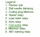
Fuse Panel Layout Diagram Parts: flasher unit, dial needle damping, coding plug motronic, starter relay, load relief relay, horn relay, fuel pump relay, motronic relay, ABS warning system.

Thursday, 12 September 2013

0 Comments
Posted in Arrangement, Art, Business

Cold Alignment Engine To GearBox

Cold Alignment Engine To GearBox

Wednesday, 11 September 2013

0 Comments
Posted in Arrangement, Art, Business

Simple Voltage to Current Converter Drives White LEDs

You sometimes need to drive a white LED from one 1.5V battery. Unfortunately, the forward voltage of a white LED is 3 to 4V. So, you would need a dc/dc converter to drive the LED from one battery. Using the simple circuit in Figure 1, you can drive one white LED or two series-connected green LEDs, using only a few components. The circuit is a voltage-to-current converter, which converts the battery voltage to a current that passes through the LED.

You can adjust this current and, thus, the brightness of the LED, by varying resistor R3. If you turn on switch S1, resistor R2 feeds base current to transistor Q2. Q2 turns on, and its collector current, via R3, turns on Q1. Now, the current through inductor L1 increases. The slope of the increase is a function of the value of L1 and the battery voltage. The current through L1 increases until it reaches a maximum value, which depends on the gain of Q1. Because the value of R3 sets the base current drawn from Q1, Q1s collector current is also limited.

White LEDs Circuit Diagram

White LEDs Circuit Diagram


Once the current through L1 reaches its maximum value, the slope of the current through L1 changes. At that instant, the voltage on L1 switches to a negative polarity forced by the changed slope. This negative voltage traverses capacitor C1 and turns off Q2, which in turn turns off Q1. The negative voltage on L1 increases until it reaches the forward voltage of the LED. The peak current through inductor L1 now flows through the LED and decreases to zero. Now, Q2 switches on again, via the current through R2, and the cycle starts again.

By adjusting resistor R3, you can set the peak current through L1 and the peak current through the LED. The brightness of an LED is a linear function of the current through the LED. So, adjusting the value of R3 also adjusts the brightness of the LED.

It doesnt matter which LED you use; the forward voltage on the LED always increases until the peak current through L1 flows through the LED. Different forward voltages of the LEDs yield different on-times (duty cycles) but the same peak current through the LED. With the values shown in Figure 1, the circuit oscillates at a frequency of approximately 30 kHz and delivers a 20-mA peak current through the LED.

The duty cycle depends on the ratio of the battery voltage to the forward voltage of the LED. One advantage of this circuit is that it requires no series-limiting resistor for the LED. The peak current through the LED is a function of the value of R3 and the gain of Q1.[via]

Tuesday, 10 September 2013

0 Comments
Posted in Arrangement, Art, Business

Simple Wireless TRIAC Dimmer

This project was used as a wireless light dimmer, but in principle can be used to dim resistive loads and wirelessly turn on/off loads. The current code includes a routine to dim a light bulb in a “heartbeat” pattern, with the heartbeat frequency remotely adjustable.


The top left of the schematic shows the wall outlet (US 120VAC) being stepped down with a small transformer, then full rectified and regulated. This powers the entire board from the wall. The top right shows a microcontroller, ATmega48, its programming header, and a UART connection to the microcontroller (for debugging). The bottom right shows the XBee and its basic voltage regulation (it’s 3.3V), as well as an LED that indicates when the XBee is connected.

Thursday, 5 September 2013

0 Comments
Posted in Arrangement, Art, Business

FM Transmitter Bug Circuit

Circuit Diagram 
Notes:
 This small transmitter uses a hartley type oscillator. Normally the capacitor in the tank circuit would connect at the base of the transistor, but at VHF the base emitter capacitance of the transistor acts as a short circuit, so in effect, it still is. The coil is four turns of 18swg wire wound around a quarter inch former. The aerial tap is about one and a half turns from the supply end. Audio sensitivity is very good when used with an ECM type microphone insert
  
Author: David, radio_david@yahoo.com
Source http://www.electronics-lab.com/

Wednesday, 4 September 2013

0 Comments
Posted in Arrangement, Art, Business

Solid State Relay Required Only 50uA Drive Current

This circuit demands a control current that is 100 times smaller than that needed by a typical optically isolated solid state relays. It is ideal for battery-powered systems. Using a combination of a high current TRIAC and a very sensitive low current SCR, the circuit can control about 600 watts of power to load while providing full isolation and transient protection.

Solid State Relay Circuit diagram:

Tuesday, 3 September 2013

0 Comments
Posted in Arrangement, Art, Business

Touch Sensor Switch Using Inverters

This touch sensor switch can is designed using inverters (N1, N2)and some common electronic components. In standby state at the entrances of N1 there is a signal produced by oscillator N3/N4. At the touch sensor hand capacity forms a bridge to the ground for the 1MHz signal so that the voltage signal at the entrance of N1 decreases more (at the exit of N2 is logical 1). After the release of contact, a signal charge C4 through D1 Mhz, so the output of N2 is 0 logic after short time.

Touch Sensor Switch Using Inverters Circuit Diagram


Installation can be powered with a DC voltage between 3 and 15 volts (maximum current of 2 mA is absorbed).

    Total Pageviews