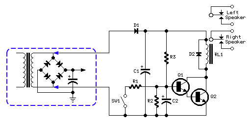
In the circuit diagram, resistor R3 and capacitor C2 form an RC network timer. When voltage is applied to the circuit, R3 allows C2 to charge to about 1.2V. The transistors Q1 and Q2 are connected in a Darlington configuration and are then non-conducting until the charge across C2 does not exceed the sum of the base-emitter voltage of Q1 and Q2, i.e. 0.6V for each transistor for a total of 1.2V.
 |
| Loudspeaker Thump Remover Circuit Diagram |
Once the voltage across C2 exceeds 1.2V, Q1 and Q2 immediately run into saturation, activating the relay RL1, which completes the circuit between the amplifier and speaker systems. The power supply circuit consists of a simple rectifier diode and a low value filter capacitor (D1 and C1). The ac voltage required is taken from the secondary winding of the transformer available in your amplifier.
In many cases, when dual supply is present and therefore the secondary winding is center tapped, the circuit can be connected across the central tap and one of the two outer leads of the winding or, on the contrary, across the whole winding. In the latter case, the available voltage will be twice the first case. This choice will affect also the coil operating voltage of the relay used.
You can choose a relay having a coil rated at 12V dc for a secondary winding ac voltage up to 15V; a 24V relay for an ac voltage up to 30V (or two SPST 12V relays wired in series, one for each channel). For higher ac voltages use a 48V relay or two SPST 24V relays wired in series. SW1 and R1 provide an optional mute facility: closing SW1 the Relay will go off and therefore the amplifier will be muted.
Notes:
- After turn on, the relay will be activated with a delay of about 3 - 5 seconds. The delay time can vary by changing the values of R3 and/or C2.
- If you do not want the mute function, SW1 and R1 can be omitted.
- If two relays wired in series are employed, the added relay must have its own clamping diode connected across the coil.
- When a voltage supply of about 48V is used, substitute BC337 transistors with BC546 types.

0 comments:
Post a Comment
Note: only a member of this blog may post a comment.