Showing posts with label usb. Show all posts

Wednesday, 2 October 2013

0 Comments
Posted in Arrangement, Art, Business

USB Power Injector For External Hard Drives

header01

A portable USB hard drive is a great way to back up data but what if your USB ports are unable to supply enough "juice" to power the drive? A modified version of the Silicon Chip Usb Power Injector is the answer. For some time now, the author has used a portable USB hard drive to back up data at work. As with most such drives, it is powered directly from the USB port, so it doesn’t require an external plug pack supply.

Projects Picture:

finished-projects

In fact, the device is powered from two USB ports, since one port is incapable of supplying sufficient current. That’s done using a special USB cable that’s supplied with the drive. It has two connectors fitted to one end, forming what is basically a "Y" configuration (see photo). One connector is wired for both power and data while the other connector has just the power supply connections. In use, the two connectors are plugged into adjacent USB ports, so that power for the drive is simultaneously sourced from both ports.

USB Cable:

usb-cables

An external USB hard drive is usually powered by plugging two connectors at one end of a special USB cable into adjacent USB ports on the computer. This allows power to be sourced from both ports. According to the USB specification, USB ports are rated to supply up to 500mA at 5V DC, so two connected in parallel should be quite capable of powering a portable USB hard drive – at least in theory.

Complete Project:

Complate project-in-box

Unfortunately, in my case, it didn’t quite work out that way. Although the USB drive worked fine with several work computers, it was a "no-go" on my home machine. Instead, when it was plugged into the front-panel USB ports, the drive repeatedly emitted a distinctive chirping sound as it unsuccessfully tried to spin up. During this process, Windows XP did recognise that a device had been plugged in but that’s as far as it went – it couldn’t identify the device and certainly didn’t recognize the drive. Plugging the drive into the rear-panel ports gave exactly the same result. The problem wasn’t just confined to this particular drive either. A newly-acquired Maxtor OneTouch4 Mini drive also failed to power up correctly on my home computer, despite working perfectly on several work computers.

Circuit diagram:

circuit diagram

The revised USB Power Injector is essentially a switch and a 5V regulator. The Vbus supply from USB socket CON1 turns on transistor Q1 which then turns on power Mosfet Q2. This then feeds a 6V DC regulated supply from an external plug pack to regulator REG1 which in turn supplies 5V to USB socket CON2.

Source: Silicon Chip 26 June 2008

Saturday, 31 August 2013

0 Comments
Posted in Arrangement, Art, Business

USB Powered Mobile Phone Battery Charger Circuit

Description 
 This simple circuit can give regulated 4.7 volts for charging a mobile phone. USB outlet can give 5 volts DC at 100mA current which is sufficient for the slow charging of mobile phones. Most of the Mobile Phone batteries are rated 3.6 volts at 1000 to 1300 mAh. These battery packs have 3 NiMh or Lithium cells having 1.2 volt rating. Usually the battery pack requires 4.5 volts at 300-500 mA current for fast charging.
But low current charging is better to increase the efficiency of the battery. The circuit described here provides 4.7 regulated voltage and sufficient current for the slow charging of the mobile phone. Transistor Q1 is used to give the regulated output. Any medium power NPN transistor like CL100, BD139, TIP122 can be used. Zener diode D2 controls the output voltage and D1 protects the polarity of the output supply. Front end of the circuit should be connected to a A type USB plug.
Connect a red wire to pin1 and black wire to pin 4 of the plug for easy polarity identification. Connect the output to a suitable charger pin to connect it with the mobile phone. After assembling the circuit, insert the USB plug into the socket and measure the output from the circuit. If the output is OK and polarity is correct, connect it with the mobile phone.
Circuit Diagram:
Parts
  • Q1 = BD139
  • D1 = 1N4001
  • D2 = 4.7V - 1/2W
  • R1 = 560R - 1/2W
  • C1 = 16V - 100uF 
 Note:
 If the polarity is incorrect, it will destroy the mobile battery. So take extreme care.

Source - http://www.extremecircuits.net/2010/02/usb-powered-mobile-phone-battery.html

    Saturday, 10 August 2013

    0 Comments
    Posted in Arrangement, Art, Business

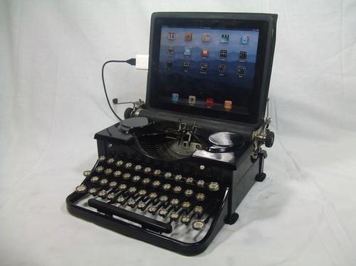
    USB Keyboard Made from Old Typewriter

    Looking for a singular gift? Here’s an vintage typewriter which has been modified to function as a USB Keyboard for PC, Mac, and even iPad. That’s very cool, isn’t it?

    Hacks and Mods: USB Keyboard Made from Old Typewriter

    In the sector of obsolescence, this USB typewriter is a groundbreaking innovation. It does no longer trade the outward look of the typewriter and is simple to put in because there is no messy wiring. The three elements of the USB typewriter are the Sensor board, the USB switches, and the Reed Switches.

    It works like a normal typewriter with all letters, numerals, and punctuation marks as neatly as shift, house, and return carriage. It’s a greater addition to your house place of business.

      Total Pageviews