The
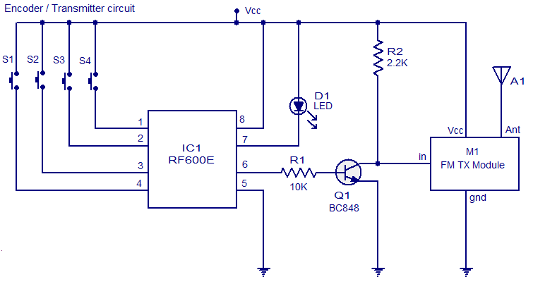
remote systems given here uses FM for the transmission. IC1 RF600E and
its associated components form the encoder circuit. Pins 1 to 4 forms
the switch inputs of IC1. When each push button switch is pressed a
corresponding code will be generated at the pin 6 which is the data
output pin. The encoded signal available at pin 6 is buffered using the
transistor Q1 and the fed to the input of a general purpose FM
transmitter module (M1). Such FM transmitter modules are very common in
the market now.
The decoder
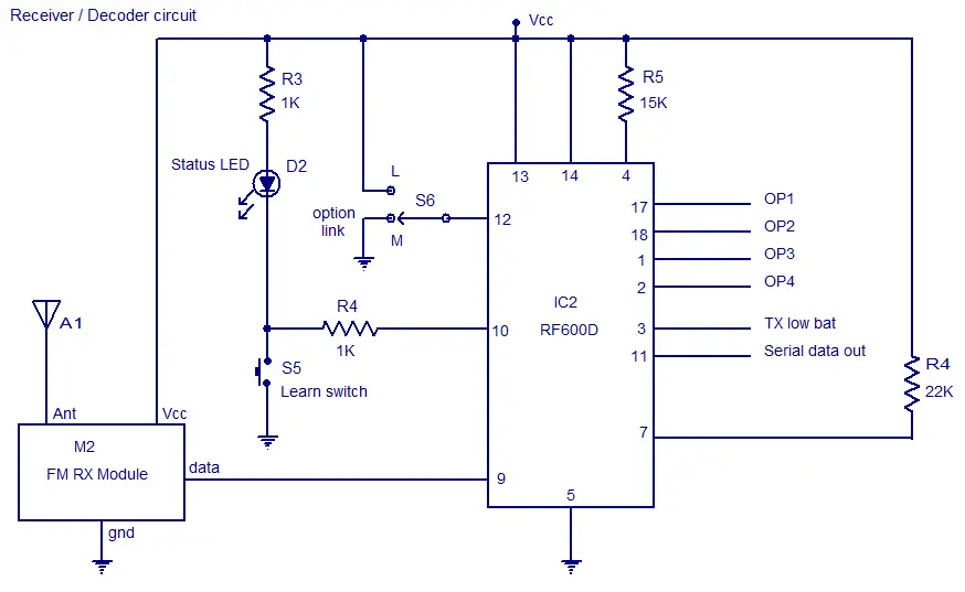
system comprises of the IC2 RF600D and its associated components. Pins
17, 18, 1 and 2 are the digital data output pins of RF600D
corresponding to the input switches S1 to S4 of the encoder/transmitter
circuits. The digital data output pins 17,18,1 and 2 are asserted low
when the relevant inputs S1 to S4 on the IC2 RF600E are asserted. M2 is
a general purpose FM receiver module which receives the transmitted
code and feds it to the data input (pin 9) of the IC2. Switch S1 can be
used to select between latching and momentary digital output function.
In latching mode digital output pins (OP1 to OP4) are only asserted
for the corresponding transmit signal. In latching mode the output
state is changed on each corresponding transmit signal. The learn
switch S5 is used to enter the decoder IC in to the “learn mode”. Learn
operation using push button switch S5 is as follows. 1) Press and release the push button switch S5. 2) The status LED D2 will glow when S5 is pressed and will remain ON when S5 is released. 3) Operate the encoder/transmitter once. 4) The status LED D2 will become OFF. 5) Operate the encoder/transmitter again. 6) The status LED will start flashing. 7)
When the flashing of status LED stops, the encoder will be successfully
taught to the decoder and the transmitter/encoder will now operate the
receiver/decoder system. Up to seven encoder/transmitters can be
learnt to each RF600D.Pin 3 of IC2 is the transmitter low battery
indicator output and pin 11 is the serial data output.
Circuit diagram.system comprises of the IC2 RF600D and its associated components. Pins
17, 18, 1 and 2 are the digital data output pins of RF600D
corresponding to the input switches S1 to S4 of the encoder/transmitter
circuits. The digital data output pins 17,18,1 and 2 are asserted low
when the relevant inputs S1 to S4 on the IC2 RF600E are asserted. M2 is
a general purpose FM receiver module which receives the transmitted
code and feds it to the data input (pin 9) of the IC2. Switch S1 can be
used to select between latching and momentary digital output function.
In latching mode digital output pins (OP1 to OP4) are only asserted
for the corresponding transmit signal. In latching mode the output
state is changed on each corresponding transmit signal. The learn
switch S5 is used to enter the decoder IC in to the “learn mode”. Learn
operation using push button switch S5 is as follows. 1) Press and release the push button switch S5. 2) The status LED D2 will glow when S5 is pressed and will remain ON when S5 is released. 3) Operate the encoder/transmitter once. 4) The status LED D2 will become OFF. 5) Operate the encoder/transmitter again. 6) The status LED will start flashing. 7)
When the flashing of status LED stops, the encoder will be successfully
taught to the decoder and the transmitter/encoder will now operate the
receiver/decoder system. Up to seven encoder/transmitters can be
learnt to each RF600D.Pin 3 of IC2 is the transmitter low battery
indicator output and pin 11 is the serial data output.


Notes.
- Assemble the circuit on a good quality PCB.
- The ICs can be operated from anything between 2V to 6.6V.
- Switches S1 to S5 are miniature push button switches.
- S6 can be a miniature two way switch.
- Transmit LED D1 will glow whenever the encoder is transmitting.
- The power supply must be properly regulated and ripple free.
- I recommend using batteries for powering the circuit.
- Go through the datasheets of RF600E and RF600D before attempting this circuit.


0 comments:
Post a Comment
Note: only a member of this blog may post a comment.